Interference rejection device, radar device, and target finding method

a radar device and interference detection technology, applied in measurement devices, using reradiation, instruments, etc., can solve the problems of difficult detection of interference signals and inability to detect interference signals superposed over echo signals

Active Publication Date: 2013-12-26
FURUNO ELECTRIC CO LTD
View PDF3 Cites 34 Cited by
  • Summary
  • Abstract
  • Description
  • Claims
  • Application Information

AI Technical Summary

Benefits of technology

[0018]It is an object of the present invention to provide an interference rejection device, a radar device and a target finding method with which an interference signal that is superposed over an echo signal can be detected even when there is little difference between the amplitude of the echo signal and the amplitude of the interference signal.
[0020]With this interference rejection device, since the detector compares the change amounts calculated by the change amount calculator for the plurality of sweeps in the detection of the radar interference occurring between the first distance and the second distance, the variance in the distance direction in the at least one of the amplitude and the phase that occurs when an interference signal has been superposed over an echo signal can be ascertained, and the interference signal can be detected, even when there is little difference between the at least one of the amplitude and the phase of the echo signal and the at least one of the amplitude and the phase of the interference signal.
[0023]With the present invention, an interference signal that is superposed over an echo signal can be detected even when there is little difference between the at least one of the amplitude and the phase of the echo signal and the at least one of the amplitude and the phase of the interference signal.

Problems solved by technology

However, if the interference rejection processing discussed above is applied to the pulse compression radar, not only the interference signal, but also the echo signal will end up being changed, so the following distortion occurs in the MF output.
However, with the disturbance signal rejection system (interference signal rejection method) discussed in Patent Literature 1, the decision is made based only on the magnitude of the amplitude of the target data (whether or not a threshold has been exceeded), so it is difficult to detect an interference signal when the interference signal is superposed over an echo signal.
However, with the interference signal rejection method of Patent Literature 1, if there is little difference between the amplitude of the echo signal and the amplitude of the interference signal, the magnitude of the amplitude of the target data will be greatly influenced by the amplitude of the echo signal, and the interference signal that is superposed over the echo signal cannot be detected.

Method used


Image

  • Interference rejection device, radar device, and target finding method
  • Interference rejection device, radar device, and target finding method
  • Interference rejection device, radar device, and target finding method

Examples


first embodiment

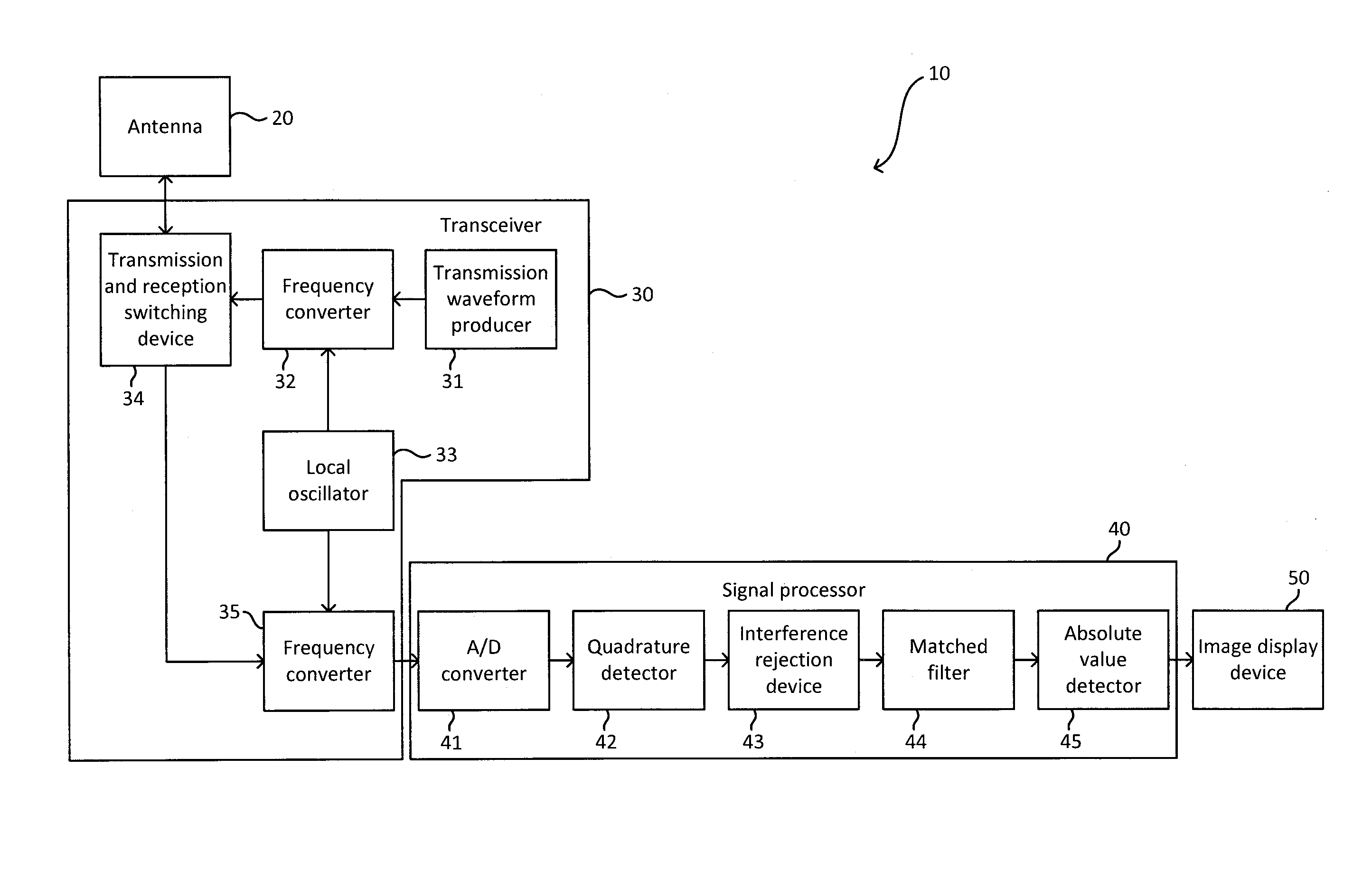
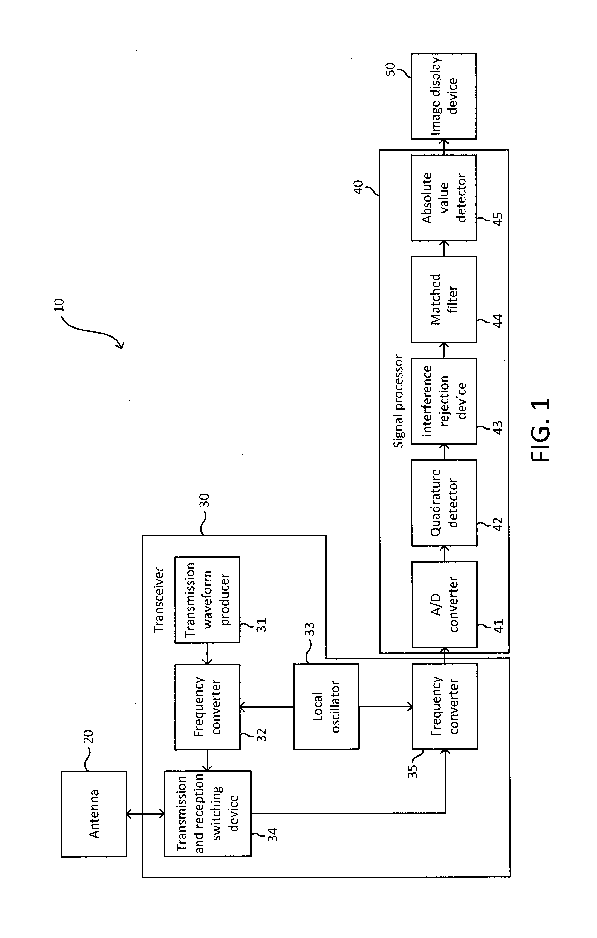
[0043]A radar device in accordance with a first embodiment of the present invention will be described through reference to the drawings. FIG. 1 is a simplified block diagram of the configuration of this pulse compression radar device (chirp radar). As shown in FIG. 1, a pulse compression radar device 10 includes an antenna 20, a transceiver 30, a signal processor 40, and an image display device 50. The pulse compression radar device 10 shown in FIG. 1 is provided to a ship, for example, and is used as a marine radar device for detecting targets such as other ships or buoys at sea, or land or the like. The pulse compression radar device 10 searches for targets using a chirp signal that has undergone frequency modulation, for example. The modulation and demodulation of pulse signals in the pulse compression radar device 10 are carried out by pulse compression processing. The various elements constituting the pulse compression radar device 10 will now be described in detail. A marine r...

modification example 1-1

[0106]In the above embodiment, a case in which the pulse compression radar device 10 used the chirp signal was described, but the modulated pulse signal is not limited to the chirp signal. The pulse compression radar device 10 can have the same configuration if the transmission waveform producer 31 produces a nonlinear frequency modulation signal, a code modulation signal, or another such modulation signal. In addition to the pulse compression radar device, the above method can also be applied to a radar device that makes use of unmodulated pulse signals.

modification example 1-2

[0107]In the above embodiment, the amplitude of the received signal was obtained from the complex received signals detected by quadrature using the amplitude calculator 61, but some other method can be used to obtain the amplitude value. For instance, the amplitude of the received signal can be obtained by performing envelope detection in which only amplitude information is taken out, or the like, and the method is not limited to one in which the amplitude is found from the absolute values of the complex received signals I and Q.


PUM


Abstract

An interference rejection device includes a change amount calculator, a detector, and a rejecter. The change amount calculator is configured to find change amounts in at least one of amplitude and phase of received signals of a plurality of sweeps in a distance direction between a first distance and a second distance. The detector is configured to detect radar interference occurring between the first distance and the second distance by comparing the change amounts calculated by the change amount calculator between the plurality of sweeps. The rejecter is configured to reduce the amplitude of the received signal corresponding to a position of the radar interference.

Description

CROSS-REFERENCE TO RELATED APPLICATIONS[0001]This application claims priority to Japanese Patent Application No. 2012-139905 filed on Jun. 21, 2012. The entire disclosure of Japanese Patent Application No. 2012-139905 is hereby incorporated herein by reference.BACKGROUND[0002]1. Field of the Invention[0003]The present invention relates to an interference rejection device that rejects radar interference occurring between a plurality of radar devices, and to a radar device equipped with an interference rejection device, and to an interference rejection method for rejecting radar interference.[0004]2. Background Information[0005]A conventional marine radar transmits a sine wave pulse by using a magnetron. The amplitude of the interference signal produced when this radar (hereinafter referred to as a magnetron radar) is affected by another magnetron radar (such as a radar installed on a nearby ship) is far greater than the amplitude of a signal pertaining to a wave reflected from a targ...

Claims


Application Information

Patent Timeline
Patent Type & Authority Applications(United States)
IPC IPC(8): G01S13/10G01S13/937
CPCG01S13/10G01S7/023G01S7/2926G01S7/2927G01S13/28G01S13/937
Inventor KOJIMA, TATSUYA
Owner FURUNO ELECTRIC CO LTD
Why Eureka
Try Eureka