Synchronized isolated ac-ac converter with variable regulated output voltage

Active Publication Date: 2013-12-26
DELTA ELECTRONICS (THAILAND) PUBLIC CO LTD
View PDF11 Cites 10 Cited by
  • Summary
  • Abstract
  • Description
  • Claims
  • Application Information

AI Technical Summary

Benefits of technology

[0020]In a preferred embodiment, the resonant half bridge comprises a high frequency transformer, i. e. a transformer that is specially designed to operate at frequencies of 40 kHz and higher, preferably 100 kHz and higher. Such a transformer has the advantage to improve the energy-efficiency of the resonant half bridge and the AC-AC converter. It is of course also possible to use a standard transformer in the resonant half bridge.
[0021]In a typical embodiment, the resonant half bridge comprises a high frequency switch, i. e. a switch that is designed to operate at frequencies of 40 kHz or more, preferably 100 kHz or more. Preferably, the resonant half bridge comprises two high frequency switches which are typically MOSFETs. The switches are preferably driven by a control structure providing a fixed duty cycle. The advantage of using such high frequency switches is that the energy-efficiency of the resonant half bridge and the AC-AC converter are improved.
[0022]In a particularly preferred embodiment, the resonant half bridge comprises a voltage doubler configuration on its secondary side and/or on the secondary side of the high frequency transformer. The voltage doubler configuration preferably comprises two diodes and/or two capacitors. Such a voltage doubler configuration has the advantage that it is not necessary to foresee any tapped secondary winding in the high frequency transformer. Imbalances caused by different leakage inductances are thereby avoided. The capacitors of the voltage doubler configuration typically have capacitances in the range of 0.1 to 250 μF, preferably around 1 μF.
[0023]In a

Problems solved by technology

The disadvantage with the phase angle control method is that the utility mains current contains harmonics which are not present in the utility mains voltage.
Other loads, which are connected to the utility mains, suffer from these negative effects of the harmonics generated.
In order to filter these harmonics, one needs to use very large filter circuit components making the overall solutions bulky and causing more electric losses.
The disadvantage with the integral cycle control is tha

Method used


Image

  • Synchronized isolated ac-ac converter with variable regulated output voltage
  • Synchronized isolated ac-ac converter with variable regulated output voltage
  • Synchronized isolated ac-ac converter with variable regulated output voltage

Examples


Example

[0031]In the figures, the same components are given the same reference symbols.

PREFERRED EMBODIMENTS

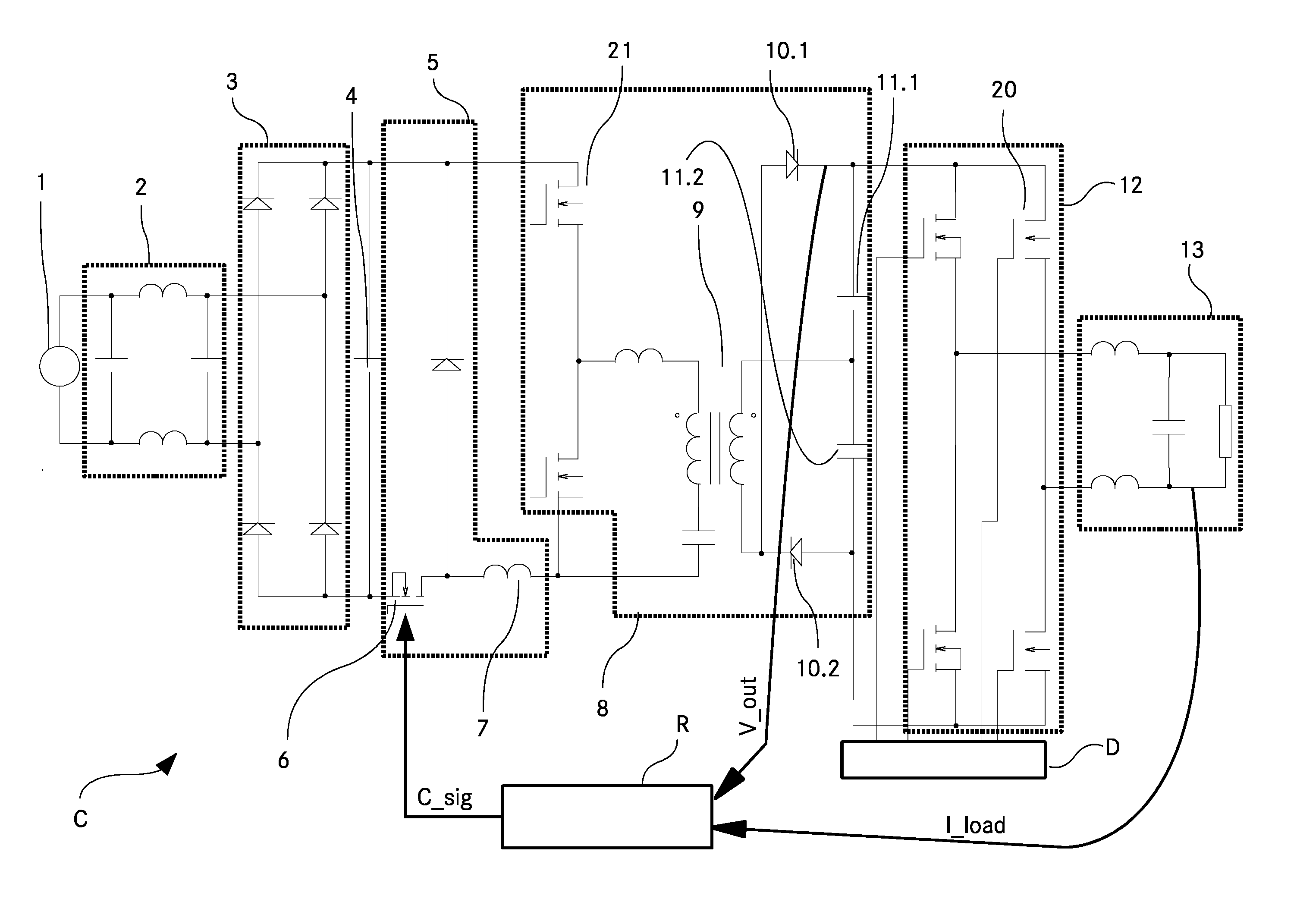
[0032]FIG. 1 shows a schematic wiring diagram of an AC-AC converter C according to the invention. A utility mains 1 is the power source to the input of the AC-AC converter C. The alternating current supplied by the utility mains 1 is cycled through the low pass filter 2 which serves for filtering electromagnetic interference noise. The utility mains typically has a frequency of 40 Hz to 60 Hz.

[0033]A bridge rectifier 3 after the low pass filter 2 converts the filtered alternating sinusoidal voltage to a unidirectional rectified sine wave. The frequency of this unidirectional rectified sine wave is double the utility mains frequency.

[0034]Connected in parallel with the bridge rectifier 3 is a current supply capacitor 4 which provides the necessary high frequency current for the next stage of the AC-AC converter—the step down converter 5—by providing a continuously flowing input current...


PUM


Abstract

In an AC-AC converter comprising a primary side, a secondary side and a regulator, wherein the regulator comprises a voltage regulation circuit configured to determine an error voltage based on an at least partially alternating feedback voltage fed into the regulator from the secondary side of the AC-AC converter and to supply this error voltage and/or an information about this error voltage to the primary side of the AC-AC converter, the regulator comprises an averaging circuit configured to determine an average DC voltage based on the feedback voltage.

Description

TECHNICAL FIELD[0001]The invention relates to AC-AC converters comprising a primary side, a secondary side and a regulator, wherein the regulator comprises a voltage regulation circuit configured to determine an error voltage based on a feedback voltage fed into the regulator from the secondary side of the AC-AC converter and to supply this error voltage and / or an information about this error voltage to the primary side of the AC-AC converter.BACKGROUND ART[0002]In certain technical applications, for example but not exclusively printers, heaters or lamps, there is a need for AC-AC converters which are able to supply output voltages of variable amplitudes which otherwise follow the sinusoidal waveform of the utility mains, especially in terms of phase and frequency.[0003]There are techniques such as phase angle control or integral cycle control which are typically used in alternating current networks to provide regulated output voltage.[0004]The disadvantage with the phase angle cont...

Claims


Application Information

Patent Timeline
IPC IPC(8): H02M5/458H02M1/00
CPCH02M5/458H02M5/225H02M1/0025
Inventor BHATT, MALHARSPRINGETT, NIGELBITSCH, WOLFGANG
Owner DELTA ELECTRONICS (THAILAND) PUBLIC CO LTD
Why Eureka
Try Eureka