

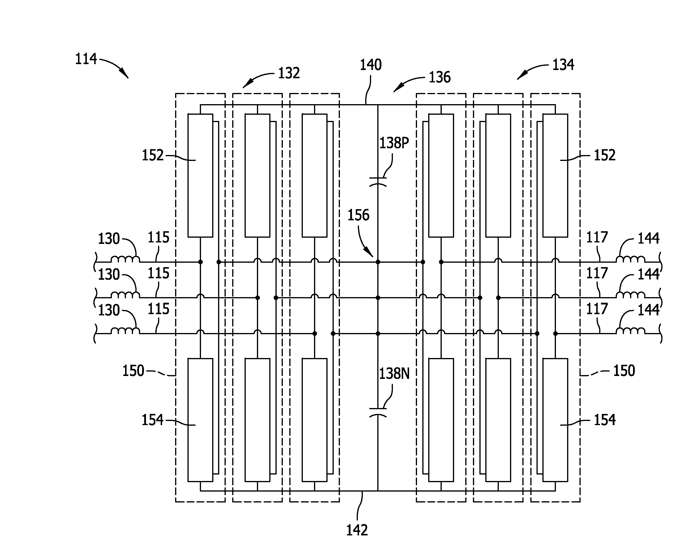
Three-level phase leg for a power converter
a power converter and phase leg technology, applied in the direction of printed circuit board receptacles, electrical apparatus construction details, support structure mounting, etc., can solve the problems of harmonics affecting power quality, increasing switching losses and voltage overshoots, and increasing challenges, so as to facilitate the reduction of energy stored within the loop current and facilitate flux cancellation
- Summary
- Abstract
- Description
- Claims
- Application Information
AI Technical Summary
Benefits of technology
Problems solved by technology
Method used
Image

Examples
Embodiment Construction
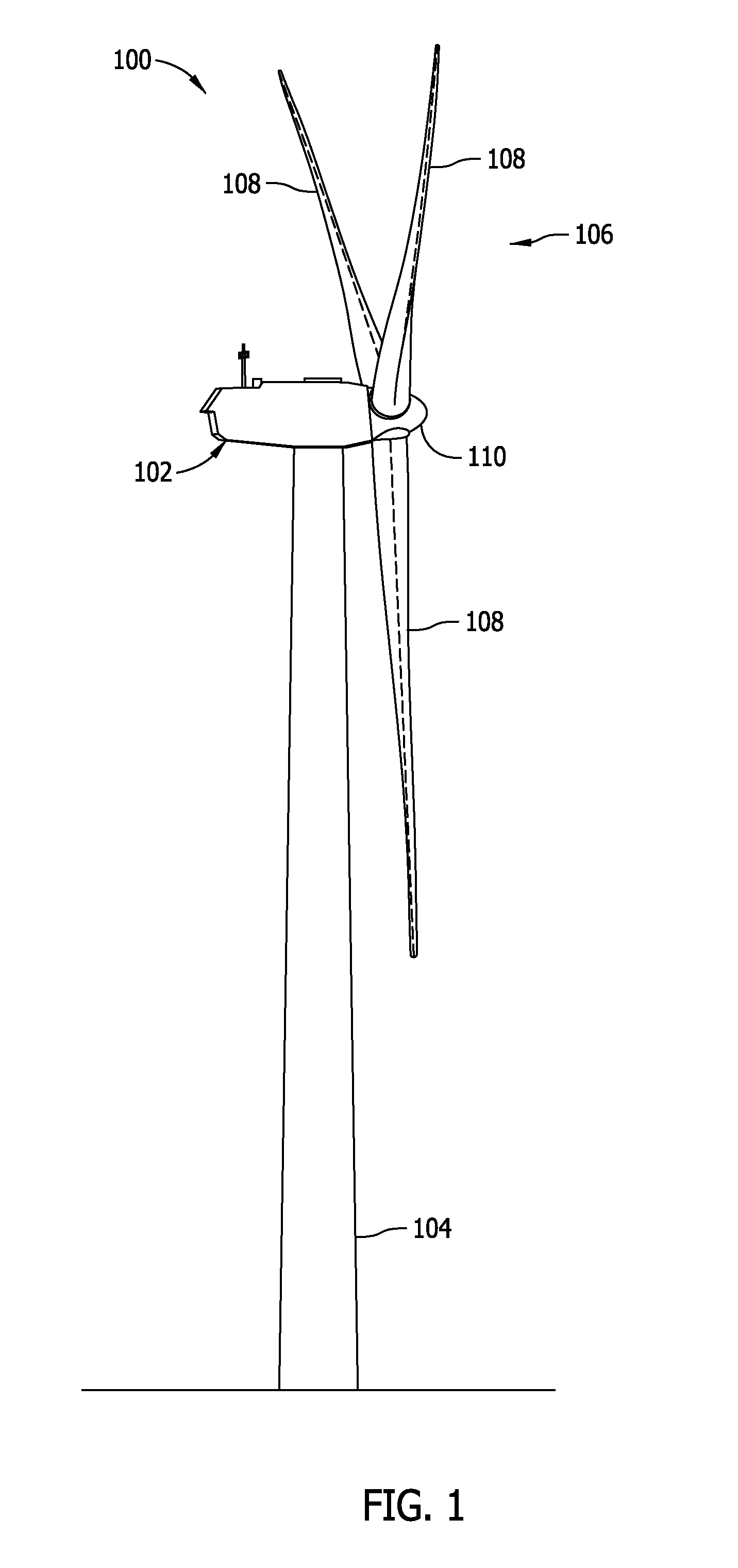
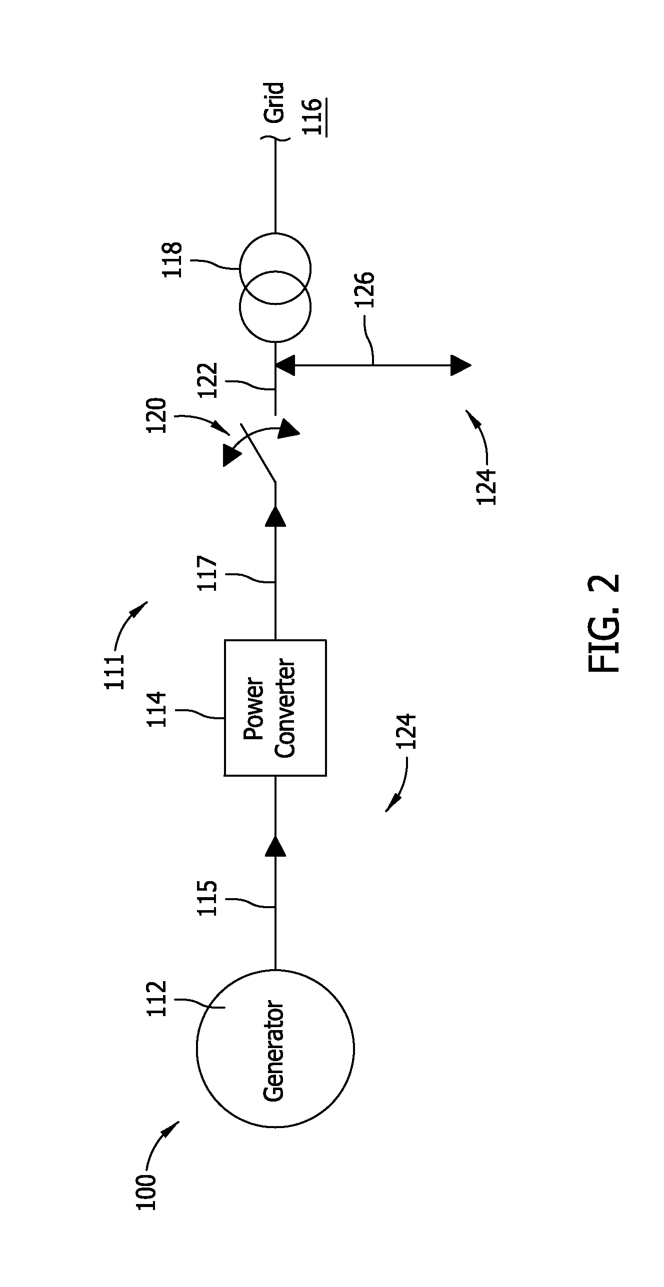
[0019]As used herein, the term “blade” is intended to be representative of any device that provides reactive force when in motion relative to a surrounding fluid. As used herein, the term “wind turbine” is intended to be representative of any device that generates rotational energy from wind energy, and more specifically, converts kinetic energy of wind into mechanical energy. As used herein, the term “electric power generation device” is intended to be representative of any device that provides electric power derived from an energy resource. As used herein, the term “wind turbine generator” is intended to be representative of any wind turbine that includes an electric power generation device that generates electrical power from rotational energy generated from wind energy, and more specifically, converts mechanical energy converted from kinetic energy of wind to electrical power.
[0020]Technical effects of the apparatus and systems described herein include at least one of: (a) facil...
PUM
 Abstract
Description
Claims
Application Information