
Optical method for additive manufacturing of complex metallic shapes using a gaseous medium

a technology of additive manufacturing and gaseous medium, which is applied in the direction of liquid/solution decomposition chemical coating, solid-state diffusion coating, coating, etc., can solve the problems of significant waste of material, and achieve the effects of high density, high strength and high quality nickel

Inactive Publication Date: 2013-12-26
DEEP SPACE IND
View PDF3 Cites 19 Cited by
  • Summary
  • Abstract
  • Description
  • Claims
  • Application Information

AI Technical Summary

Benefits of technology

The Invention is a new 3D metal printing technology that produces high-density, high-strength, high-quality metal parts. Unlike other 3D metal printing technologies, the Invention uses a low-temperature process where a gaseous medium containing the metal is heated via lasers or optical patterning mechanisms to decompose the gas and deposit the metal at the heated point. The laser beam is manipulated to transcribe a pattern of heat, and the pattern is changed with time such that a desired 3D product is produced from computer-resident design specifications. The Invention is different from other 3D metal printing technologies because it avoids the necessity of completely melting the bulk metal and can be used to create high-strength, high-temperature-capable parts.

Problems solved by technology

Subtractive and traditional manufacturing and machining processes thus produce a significant amount of wasted material.

Method used


Image

  • Optical method for additive manufacturing of complex metallic shapes using a gaseous medium
  • Optical method for additive manufacturing of complex metallic shapes using a gaseous medium

Examples


Embodiment Construction

I. A General Explanation of the Invention and How to Practice It

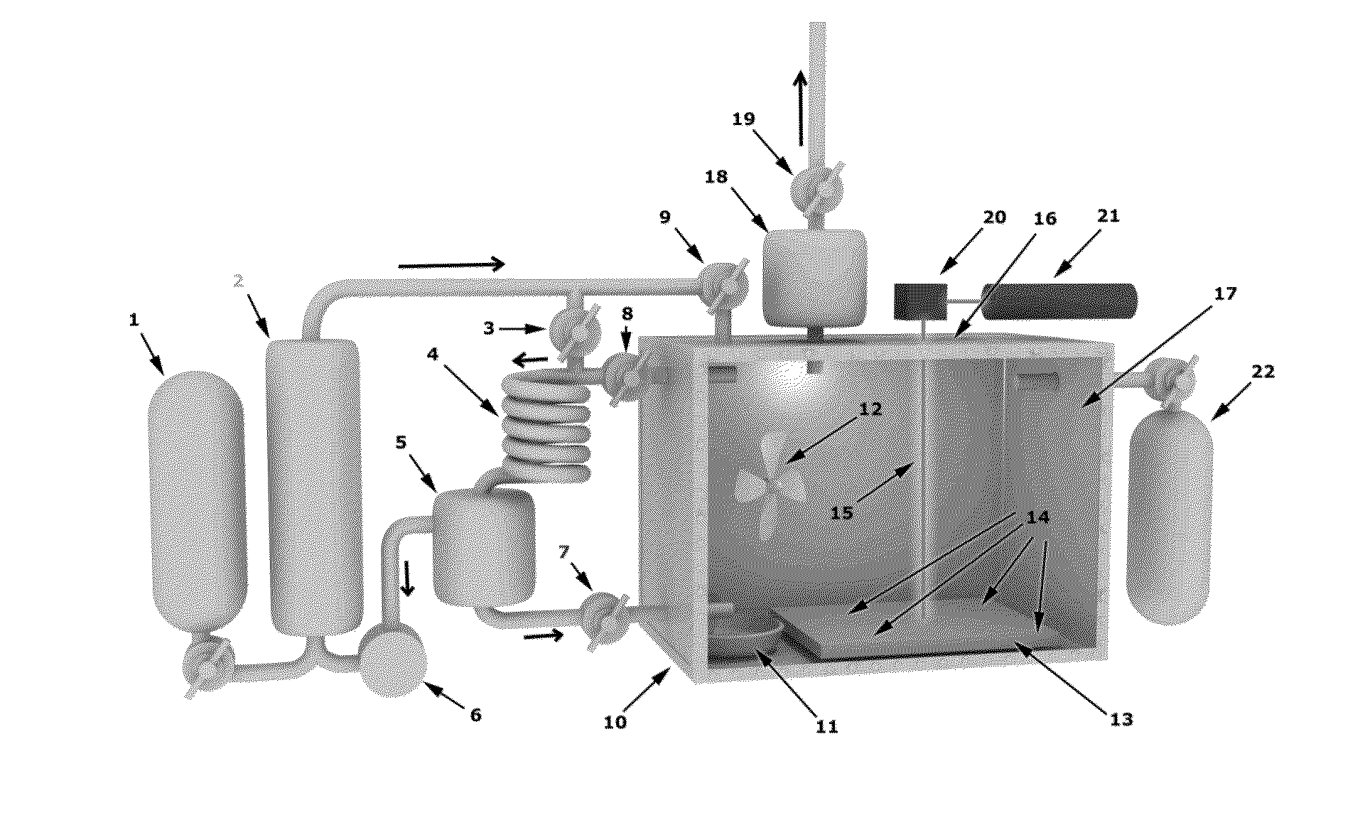
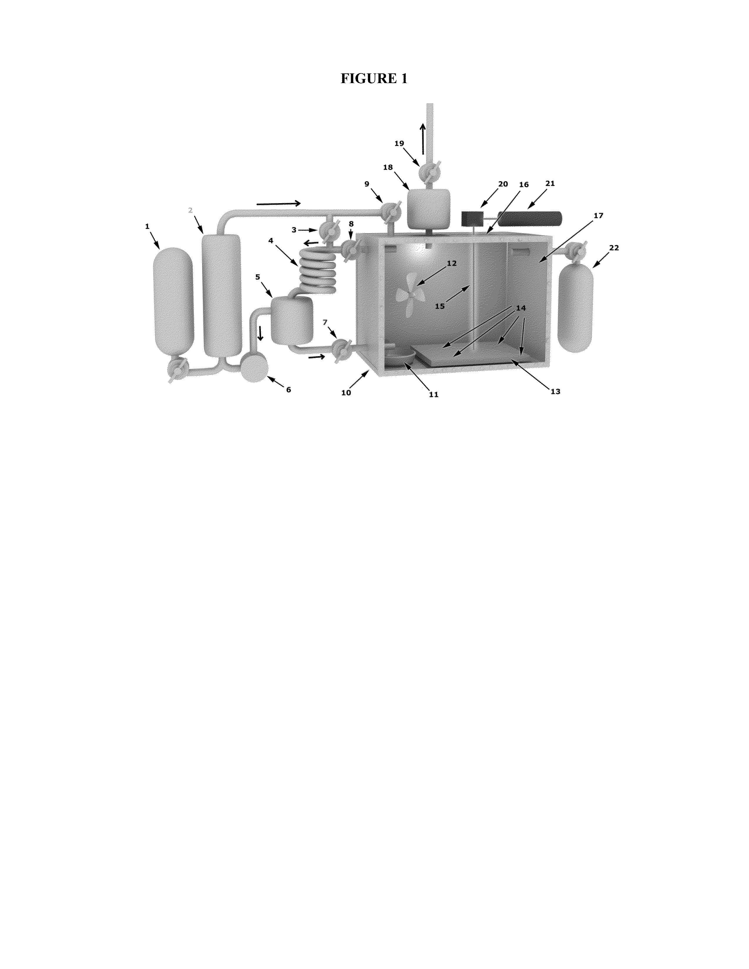
[0028]The present invention is a new method for an additive manufacturing process of complex metallic shapes utilizing advanced computer assisted design. The process of the present invention deposits metal from a vapor in a precise 3d shape. Using a metal source feedstock, a unique laser (or other optical patterning method) to metal carbonyl (or other gas) vapor process allows for a new method of 3d printing. The metal deposition on a cold substrate is mediated directed by laser raster (or other optical) heating (or energy deposit) to build a free form object using a CAD design process to measure and observe the process.

[0029]The present invention seeks to create a unique additive manufacturing capability utilizing common metallic feedstock which is then sublimated by conversion to carbonyl gas and then subsequently deposited by using modifications of known 3d printing processes. By utilizing metal carbonyl vapor (or ot...


PUM

PropertyMeasurementUnit
structureaaaaaaaaaa
energyaaaaaaaaaa
thermal energyaaaaaaaaaa

Abstract

The present invention is a method for additive manufacturing in which a metal feedstock is converted to a carbonyl compound (or other gaseous media) and then optical heat patterns are used to direct the deposition of the contained metal into an arbitrary 3-D structure.The optical methods used to guide the metal deposit may include one or more laser beams acting independently or in concert, and / or other optical technologies to apply a pattern of thermal energy, including LCD, LED, LCoS, DLP, or even CRT projection technologies.The metals which may be deposited are limited to those which have compounds which are gaseous at moderate temperatures and which decompose (to a gas and the metal) upon the application of heat or specific chemical binding energies via optical means. Such compounds include (but are not limited to) nickel tetracarbonyl, iron pentacarbonyl, cobalt carbonyl, titanium iodide, and platinum chloro-carbonyl.

Description

BACKGROUND OF THE INVENTION[0001]Traditional manufacturing methods are subtractive, meaning that a material or a group of materials must be removed until a desired product remains. Subtractive and traditional manufacturing and machining processes thus produce a significant amount of wasted material. More recently, additive manufacturing methods have become increasingly popular. In additive manufacturing, a material is deposited on a substrate to form a desired object. Additive manufacturing methods only deposit material needed to manufacture the product, and thus do not waste materials. Detailed computer assisted design (CAD) instructions can be input into additive manufacturing machines to create complex manufactured objects of very high complexity and quality.[0002]It is therefore an object of the present invention to provide an additive manufacturing system and method that makes use of a common metal feedstock that can be converted to a carbonyl vapor (or other gaseous media) thr...

Claims


Application Information

Patent Timeline
Patent Type & Authority Applications(United States)
IPC IPC(8): C23C18/14
CPCC23C18/14C23C16/483C23C16/4418C23C16/16B33Y70/00
Inventor COVEY, STEPHEN DARRELL
Owner DEEP SPACE IND
Learn More