Compressed gas cooling apparatus

a cooling apparatus and compressed gas technology, applied in lighting and heating apparatus, ventilation systems, heating types, etc., can solve the problems of increased power consumption and pressure loss, and achieve the effect of reducing pressure drop and reducing pressure drop

Inactive Publication Date: 2014-01-02
PRAXAIR TECH INC
View PDF7 Cites 35 Cited by
  • Summary
  • Abstract
  • Description
  • Claims
  • Application Information

AI Technical Summary

Benefits of technology

[0008]The present invention provides a compressed gas cooling apparatus having use as an intercooler or an after-cooler. The apparatus is provided with an inlet section and an outlet section. The inlet section has an inlet to receive a gas from an upstream compression stage and the outlet section has an outlet to discharge the gas, after having been cooled to a downstream compression stage. A heat exchanger connects the inlet section to the outlet section and has gas passages communicating between the inlet section and the outlet section for passage of the gas and coolant passages positioned in a heat transfer relationship with the gas passages for passage of a coolant to cool the gas passing through the gas passages through indirect heat exchange with a coolant. The inlet section portion comprises a first inlet portion and a second inlet portion. The first inlet portion is located between the inlet and the second inlet portion and the second inlet portion located between the first inlet portion and the heat exchanger. Each of the first inlet portion and the second inlet portion has an ever increasing transverse cross-sectional flow area. The ever increasing transverse cross-sectional flow area of the second inlet portion increasing at a greater rate than the first inlet portion so that the velocity of the flow of the gas gradually decreases as the gas flows through the inlet section to a lesser extent in the first inlet portion than the second inlet portion. This inhibits separation of the flow of the gas from sidewalls of each of the first inlet portion and the second inlet portion, due to swirl imparted into the flow of the gas from the upstream compression stage to reduce pressure drop. The outlet section comprises one outlet portion of ever-decreasing transverse cross-sectional flow area for flow of the gas from the heat exchanger to the outlet such that velocity of the flow of the gas gradually increases to also reduce pressure drop.

Problems solved by technology

In air separation plants, these pressure losses must be compensated for by increased compression and therefore, increased power consumption.
What has not been appreciated, even in the publication discussed above, is that pressure losses also arise from the swirl induced into the flow entering inlet and outlet sections of the intercooler or other compressed gas cooling apparatus used in connection with a compressor.

Method used


Image

  • Compressed gas cooling apparatus
  • Compressed gas cooling apparatus
  • Compressed gas cooling apparatus

Examples


Embodiment Construction

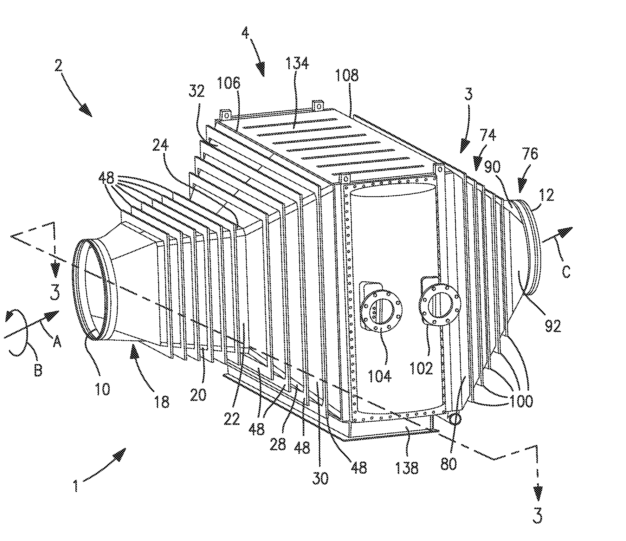
[0030]With reference to FIG. 1, a compressed gas cooling apparatus 1 in accordance with the present invention is illustrated. As mentioned above, such apparatus can function as an intercooler between compression stages or an after-cooler to cool the gas discharged from a compression stage to be used in downstream processing. Apparatus 1 has an inlet section 2, an outlet section 3 and a heat exchanger 4 connecting the inlet section 2 to the outlet section 3. The inlet section 2 has an inlet 10 to receive a gas flow “A” from an upstream compression stage, not illustrated. The upstream compression stage could be a centrifugal compressor or an axial compressor. In either case, the gas flow indicated by arrowhead “A” entering the inlet 10 has a swirl or a rotational component to the flow designated by curved arrowhead “B”. Such swirl is imparted to the flow by the rotational components of the compressor, for instance, the impeller of a centrifugal compressor.

[0031]The gas flow “A”, after...


PUM


Abstract

A compressed gas cooling apparatus in which gas from an upstream compression stage enters an inlet section from an inlet opening and flows to a heat exchanger that cools the gas. The cooled gas then flows from the heat exchanger to the outlet section where the gas is discharged from an outlet opening. Pressure drop within the apparatus is decreased by providing the inlet and outlet sections with ever increasing and decreasing cross-sectional flow areas. In order to further decrease pressure drop due to a swirl within the gas flow imparted from the upstream compression stage, the inlet section is provided with first and second subsections wherein the cross-sectional flow area of the first subsection increases at lesser rate than the second subjection. Alternatively, or in addition, the inlet section can be provided with partitions to divide the gas flow into subflows in order to lessen pressure drop from swirl.

Description

FIELD OF THE INVENTION[0001]The present invention provides a compressed gas cooling apparatus that can function as an intercooler or an after-cooler and that is used to cool a gas between or after a series of compression stages. More particularly, the present invention relates to such a cooling apparatus in which both the inlet and outlet have sections of ever-increasing and ever-decreasing area, respectively, to feed gas to and from a heat exchanger positioned between the inlet and the outlet. Even more particularly, the present invention relates to such a cooling apparatus in which the ever-increasing section of the inlet is designed to further reduce pressure losses that occur due to the swirl in the gas flow imparted by the upstream compression stage introducing compressed gas into the cooling apparatus.BACKGROUND OF THE INVENTION[0002]Large volumes of gas are compressed in a variety of industrial applications within compression systems having a series of stages with intercoolin...

Claims


Application Information

Patent Timeline
Patent Type & Authority Applications(United States)
IPC IPC(8): F25B29/00
CPCF28F2009/0292F28F9/0268F28F2009/029F04D29/5826F28F2225/08F28F17/005F28F9/0202F28D7/1623F25B29/00F28F9/0263
Inventor BAKER, ROBERT L.SURYANARAYANAN, ARUNSHELAT, MAULIK R.GOODBAND, JEFFREY C.
Owner PRAXAIR TECH INC
Why Eureka
Try Eureka