

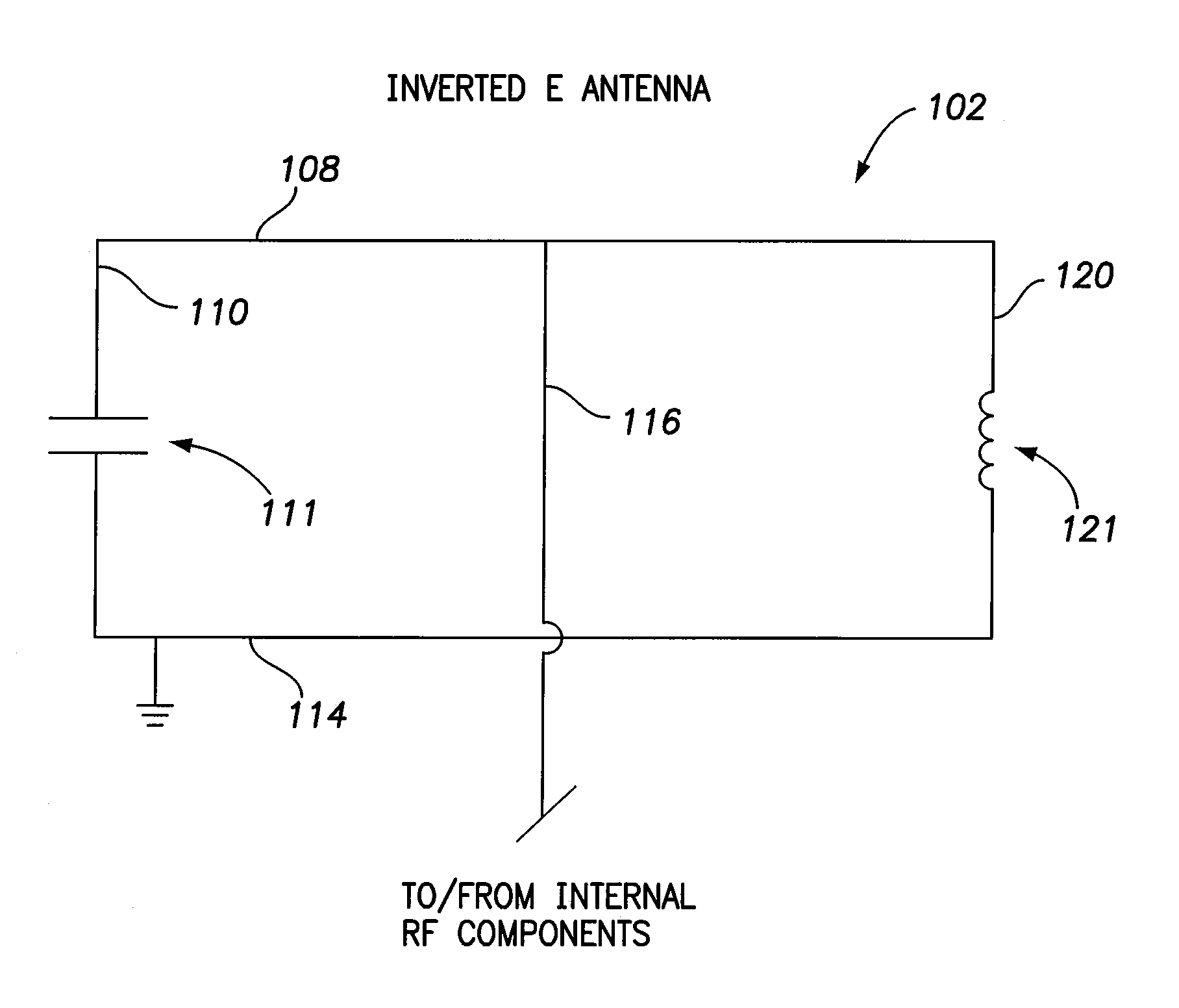
Inverted e antenna with parallel plate capacitor formed along an arm of the antenna for use with an implantable medical device
a technology of parallel plate capacitor and antenna, which is applied in the direction of resonant antenna, other domestic articles, therapy, etc., can solve the problems of device size, loss of rf communication performance, and design of such antennas, and achieve good impedance, good performance, and capacitance. the effect of larg
- Summary
- Abstract
- Description
- Claims
- Application Information
AI Technical Summary
Benefits of technology
Problems solved by technology
Method used
Image

Examples
Embodiment Construction
[0037]The following description includes the best mode presently contemplated for practicing the invention. This description is not to be taken in a limiting sense but is made merely to describe general principles of the invention. The scope of the invention should be ascertained with reference to the issued claims. In the description of the invention that follows, like numerals or reference designators will be used to refer to like parts or elements throughout.
Overview of Implantable System
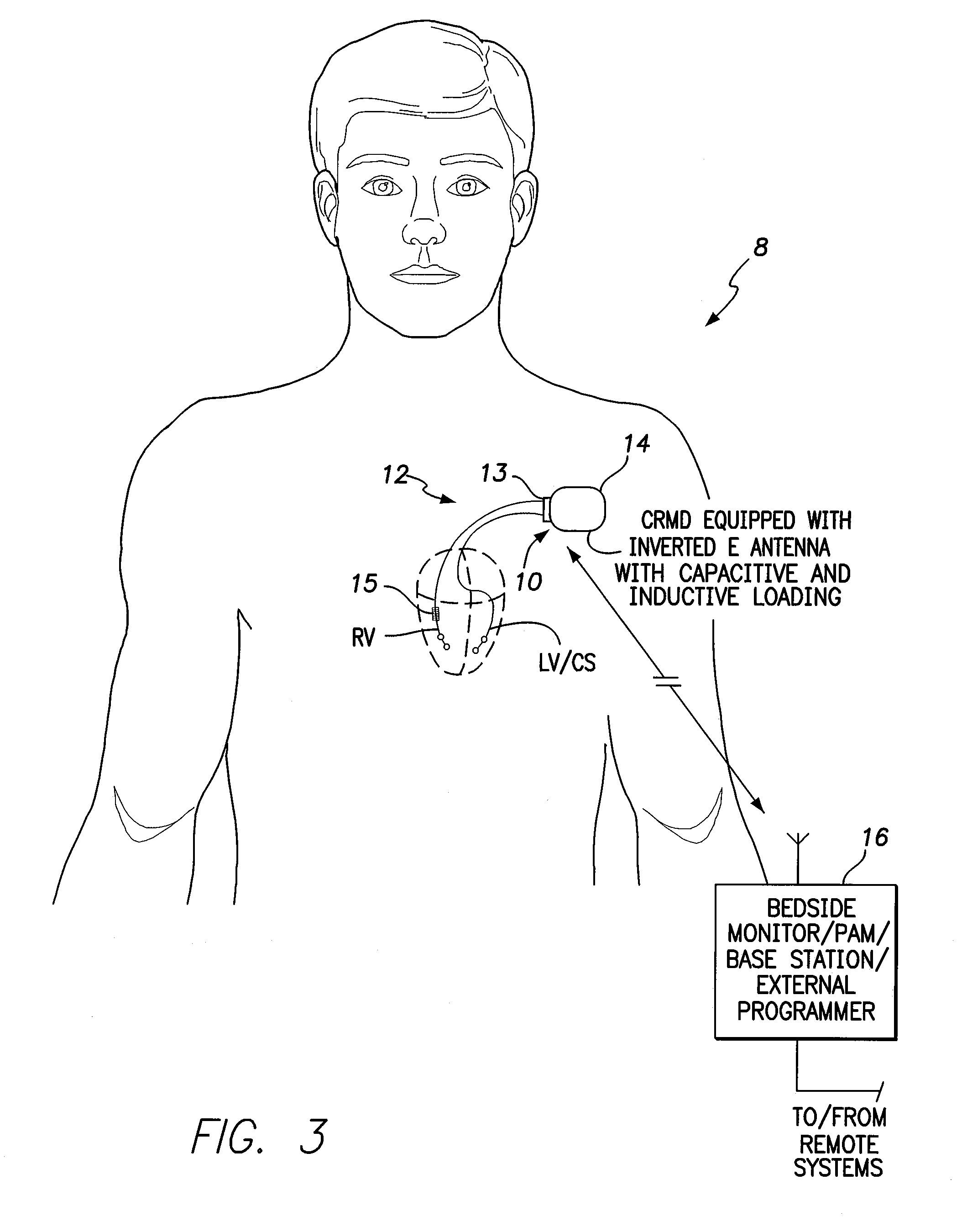
[0038]FIG. 3 illustrates an implantable medical system 8 having a CRMD 10 equipped with an inverted E antenna (not specifically shown in FIG. 3 but shown in FIGS. 4-8) for use with MICS / MedRadio transmissions and further equipped with one or more cardiac sensing, pacing and / or shocking leads 12 implanted within the heart of the patient. In some examples, the CRMD may be equipped to perform both pacing and shocking functions and may be referred to as a hybrid pacemaker / ICD or just a “hybrid.” In F...
PUM
| Property | Measurement | Unit |
|---|---|---|
| Length | aaaaa | aaaaa |
| Size | aaaaa | aaaaa |
| Electrical inductance | aaaaa | aaaaa |
Abstract
Description
Claims
Application Information