Lens Mount

a technology of lens mounting and lens body, which is applied in the field of interchangeable lens mounting system, can solve the problems of not being able to quickly interchange lenses, and the current system is not designed for miniature lenses, etc., and achieve the effect of accurate definition of the distance between the lens and the image sensor

a technology of lens mounting and lens body, which is applied in the field of interchangeable lens mounting system, can solve the problems of not being able to quickly interchange lenses, and the current system is not designed for miniature lenses, etc., and achieve the effect of accurate definition of the distance between the lens and the image sensor

US20140002676A1Active Publication Date: 2014-01-02NING ALEX

Image

  • Lens Mount
  • Lens Mount
  • Lens Mount

Examples


Embodiment Construction

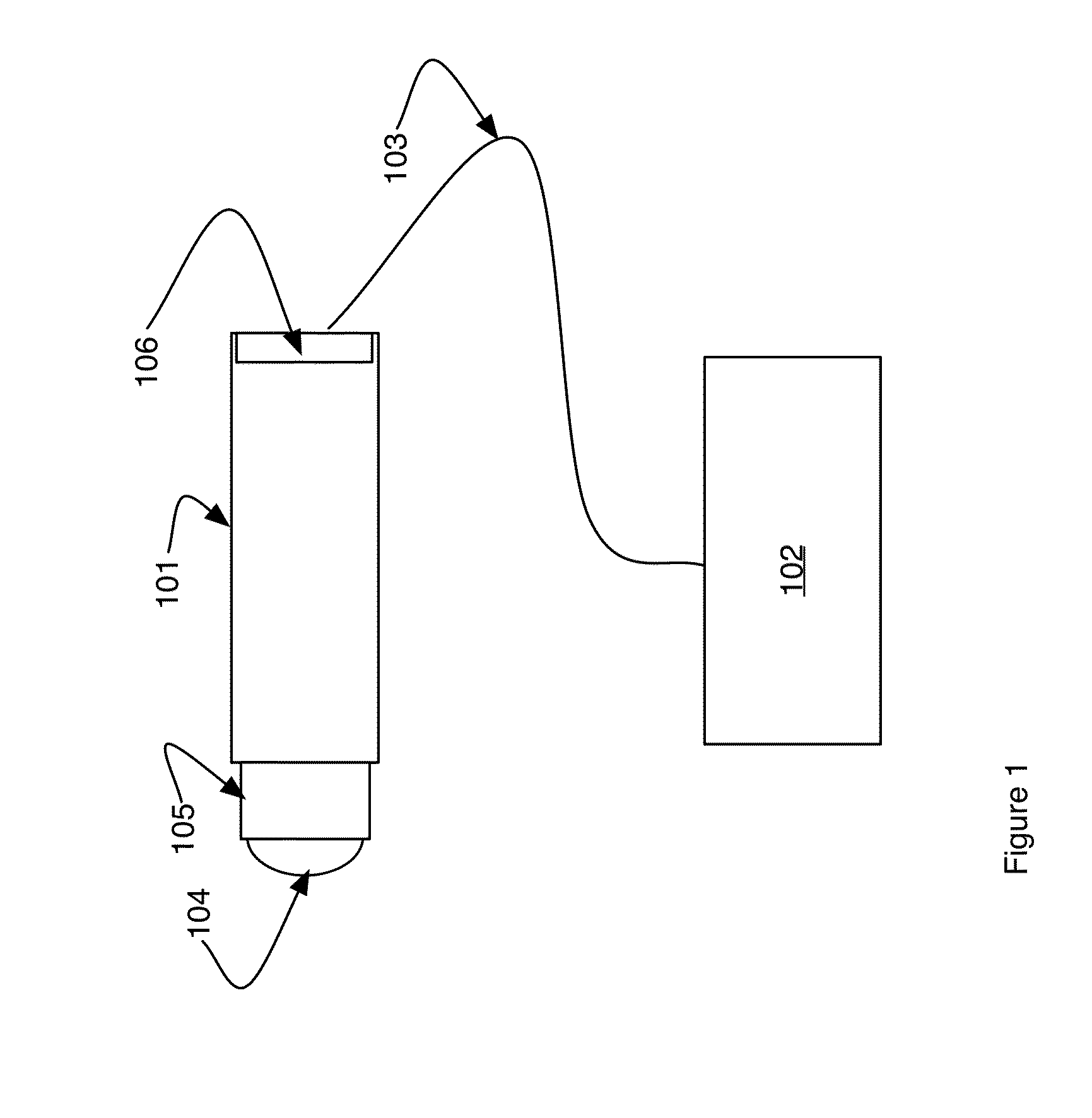
[0050]Referring to FIG. 1 an exemplary imaging system in which the present invention may be used is shown. A lens 104 is mounted in a lens body 105 that is then mounted in a lens holder 101. The lens holder is attached to an image sensor 106. The sensor is typically mounted on a printed circuit board that provides means for an electrical connection 103 to image processing electronics 102. In another embodiment, not shown, the electronics 102 are incorporated on the same circuit board as the image sensor 106 thereby providing a very compact design.

[0051]Preferred embodiments of the invention include two general components a lens body and a lens holder. The lens body is removable from the lens holder and may be interchanged with other lens bodies to provide a means for interchanging lenses. Lens bodies contain lens elements that are best used in differing imaging environments. For example one lens body may contain lens elements producing a wide-angle view and a second lens body may co...


PUM


Abstract

A lens mount design is presented. The mount can be used on a variety of imaging systems but is targeted at small camera systems such as might be used on mobile phones, cameras, sports cameras, computers and computer peripherals where interchangeable lenses are currently not common place. Embodiments include different attachment mechanisms, environmental barriers, electrical connections, a serial number marking system on the replaceable lens body and methods for using the lens mount and system.

Description

CROSS-REFERENCE TO RELATED APPLICATIONS[0001]This application is a continuation in part of U.S. PCT Application PCT / US12 / 44236, titled: Lens Mount, filed Jul. 26, 2012, by the same inventor and currently pending.BACKGROUND OF THE INVENTION[0002]1. Technical Field[0003]The present invention relates to an interchangeable lens mounting system for compact camera systems and other applications.[0004]2. Related Background Art[0005]Digital imaging cameras use solid-state image sensors such as CCD or CMOS imagers to convert optical images into electronic signals. As the resolution of the imagers increases, there is a continuous need for optical lenses with increased performance. An important characteristic of the lens is the ability to produce high-resolution images across a wide field of view. Another important characteristic is to produce such high-resolution images using a lens that is of a compact size. The lenses are increasing being incorporated into a variety of electronic devices in...

Claims


Application Information

Patent Timeline
02 Jan 2014
Publication
US20140002676A1
IPC
G02B7/14; H04N5/217
CPC
G02B7/14; H04N5/217; G03B1/00; G03B17/14; G02B7/003; H04N23/663; H04N23/57
Inventors
NING, ALEX