
Electrophotographic photosensitive member, method of producing electrophotographic photosensitive member, process cartridge, and electrophotographic apparatus

Inactive Publication Date: 2014-01-02
CANON KK
View PDF7 Cites 36 Cited by
  • Summary
  • Abstract
  • Description
  • Claims
  • Application Information

AI Technical Summary

Benefits of technology

The present invention provides an electrophotographic photosensitive member that can maintain consistent performance even after repeated use in high-temperature and high-humidity environments. This invention also provides a method of producing the electrophotographic photosensitive member, as well as a process cartridge and electrophotographic apparatus that utilize the electrophotographic photosensitive member.

Problems solved by technology

This is because general metal oxide particles have oxygen defective sites and hence can reduce the resistance.
It has been found that each of the technologies disclosed in Japanese Patent Application Laid-Open No. 2006-030700 and Japanese Patent Application Laid-Open No. 2004-219904 is liable to cause the fluctuation of the light portion potential at the time of the long-term repeated use under the high-temperature and high-humidity environment in some cases.

Method used


Image

  • Electrophotographic photosensitive member, method of producing electrophotographic photosensitive member, process cartridge, and electrophotographic apparatus
  • Electrophotographic photosensitive member, method of producing electrophotographic photosensitive member, process cartridge, and electrophotographic apparatus
  • Electrophotographic photosensitive member, method of producing electrophotographic photosensitive member, process cartridge, and electrophotographic apparatus

Examples


example 1

[0094]An aluminum cylinder having a diameter of 30 mm and a length of 357.5 mm was used as a support (conductive support).

[0095]Next, 100 parts of zinc oxide particles (specific surface area: 19 m2 / g, powder resistance: 4.7×10⁶ Q·cm) as metal oxide particles were mixed with 500 parts of toluene by stirring. 1.5 Parts of a silane coupling agent (compound name: N-(2-aminoethyl)-3-aminopropyltrimethoxysilane, trade name: KBM603, manufactured by Shin-Etsu Chemical Co., Ltd.) were added to the mixture and then the resultant was stirred for 6 hours. After that, toluene was distilled off under reduced pressure, and then the residue was heated and dried at 140° C. for 6 hours to provide surface-treated zinc oxide particles.

[0096]Next, 15 parts of a butyral resin (trade name: BM-1, manufactured by SEKISUI CHEMICAL CO., LTD.) as a polyol resin and 15 parts of a blocked isocyanate compound (trade name: Desmodur BL3575 / 1, manufactured by Sumika Bayer Urethane Co., Ltd.) whose isocyanate group h...

example 2

[0122]An electrophotographic photosensitive member was produced in the same manner as in Example 1 except that in Example 1, 0.81 part of alizarin (manufactured by Tokyo Chemical Industry Co., Ltd.) in the undercoat-layer coating liquid was changed to 0.41 part of 2,3,4-trihydroxybenzophenone (manufactured by Tokyo Chemical Industry Co., Ltd.). In addition, the ratio A / B in the undercoat layer was determined in the same manner as in Example 1. Table 1 shows the result.

examples 3 to 5

[0123]Electrophotographic photosensitive members were each produced in the same manner as in Example 2 except that in Example 2, the drying conditions were changed to conditions shown in Table 1. In addition, the ratio A / B in each undercoat layer was determined in the same manner as in Example 2. Table 1 shows the results.


PUM


Abstract

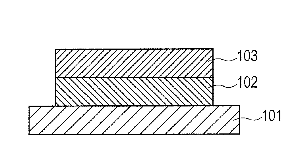
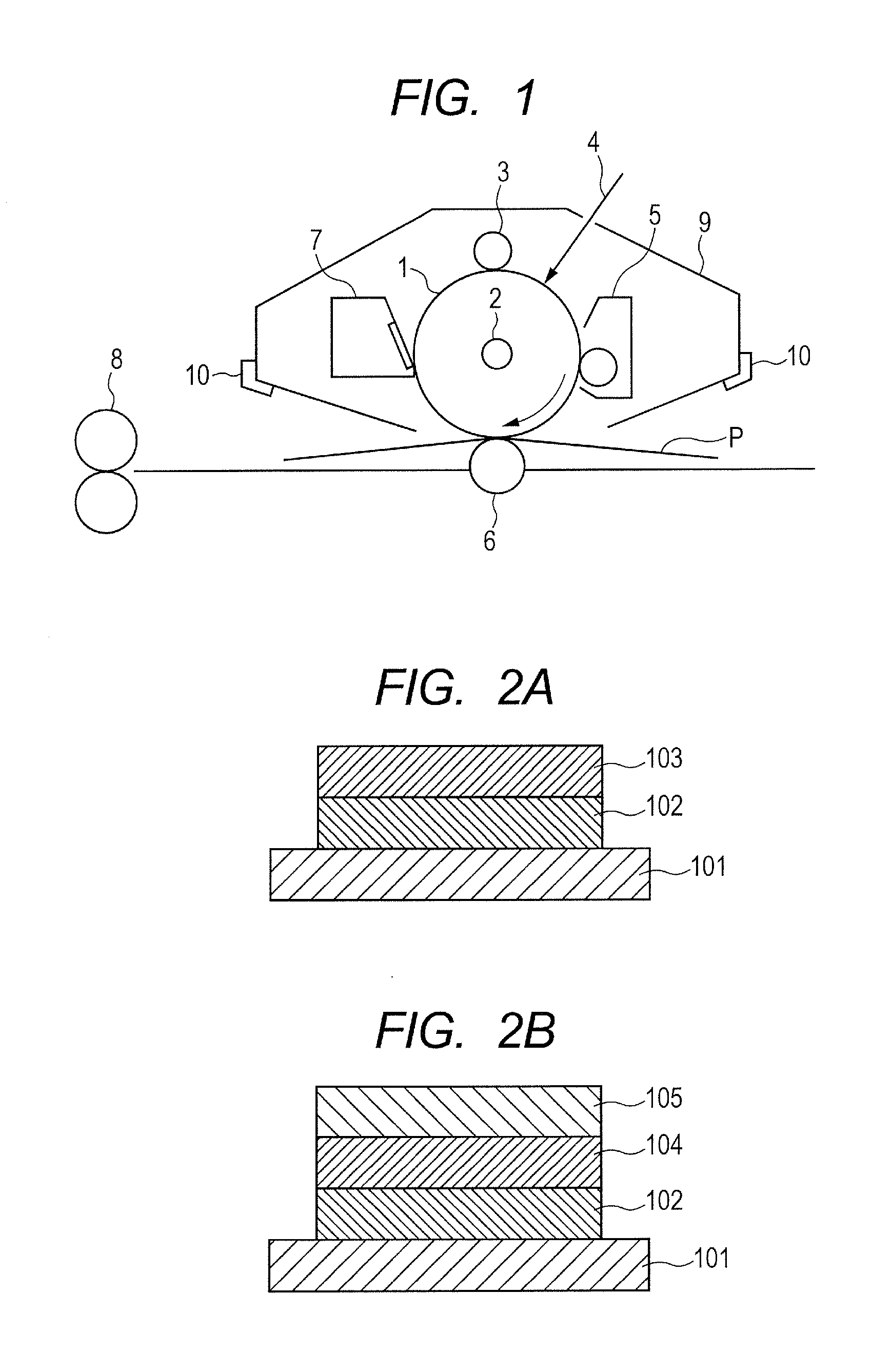
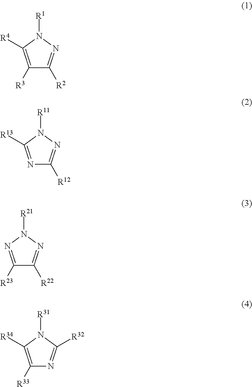
Provided is an electrophotographic photosensitive member in which an undercoat layer is a layer of which at least one selected from the group consisting of a compound represented by the formula (1), a compound represented by the formula (2), a compound represented by the formula (3) and a compound represented by the formula (4) can be detected by gas chromatography analysis when the undercoat layer is heated at 150° C. for 60 minutes by headspace method.

Description

BACKGROUND OF THE INVENTION[0001]1. Field of the Invention[0002]The present invention relates to an electrophotographic photosensitive member, a method of producing an electrophotographic photosensitive member, and a process cartridge and an electrophotographic apparatus each having an electrophotographic photosensitive member.[0003]2. Description of the Related Art[0004]An electrophotographic photosensitive member (organic electrophotographic photosensitive member) having an undercoat layer containing metal oxide particles and a photosensitive layer containing a charge generating substance and a charge transporting substance formed on the undercoat layer is sometimes used as an electrophotographic photosensitive member to be used in an electrophotographic apparatus.[0005]The undercoat layer is provided for adjustment of an electric resistance (hereinafter abbreviated as “resistance”) as one purpose and incorporation of the metal oxide particles into the undercoat layer serves to re...

Claims


Application Information

Patent Timeline
IPC IPC(8): G03G15/00G03G21/18
CPCG03G5/04G03G5/142G03G5/144G03G5/06G03G5/10G03G15/00G03G21/18
Inventor TOKIMITSU, RYOICHIISHIDUKA, YUKAKITAMURA, WATARUKAKU, KENICHIMURAKAMI, MAI
Owner CANON KK
Learn More