Cardiac valve support structure

a support structure and heart valve technology, applied in the field of cardiac valve support structure, can solve the problems of second dilatation of the mitral valve annulus, relatively more difficult to properly seat a replacement cardiac valve in the native mitral valve annulus, and difficult to achieve the effect of preventing paravalvular leakage and preventing leakage therebetween

Inactive Publication Date: 2014-01-02
MVALVE TECH
View PDF5 Cites 316 Cited by
  • Summary
  • Abstract
  • Description
  • Claims
  • Application Information

AI Technical Summary

Benefits of technology

[0050]In a further preferred embodiment of the present invention, one or both of the first and second annular support elements are fitted with at least one wing-like drape element made of a biocompatible fabric. The drape functions as a sealing element, positioned between the support element and the mitral annulus, thereby preventing paravalvular leakage after implantation of the valve support in the mitral annulus.
[0051]In one preferred embodiment of this aspect of the invention, a single drape element is attached to the entire circumference of the support element. In another preferred...

Problems solved by technology

Regurgitation can also be cause by dilatation of the left ventricle, which can lead to secondary dilatation of the mitral valve annulus.
Unlike the aortic valve, however, the mitral valve annulus does not provide a good landmark for positioning a replacement valve.
The thinner mitral valve annulus makes it relatively more difficult to properly seat a replacement cardiac valve in the native mitral valve annulus.
The general anatomy of the mitral valve annulus also makes it more difficult to properly anchor a replacement heart valve in place.
The larger mitral valve annulus makes it difficult to securely implant current percutaneously delivered valves in the...

Method used


Image

  • Cardiac valve support structure
  • Cardiac valve support structure
  • Cardiac valve support structure

Examples


Embodiment Construction

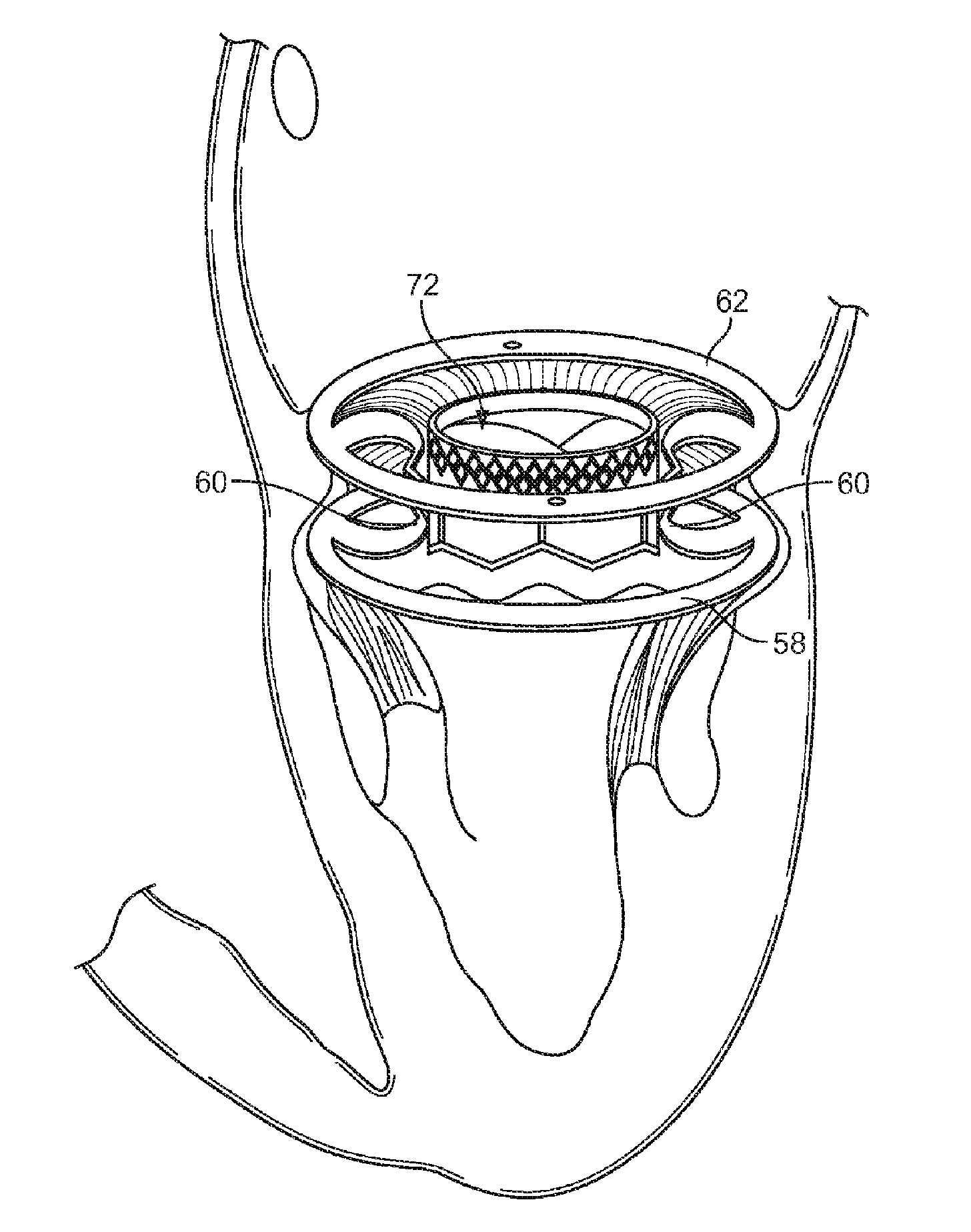
[0140]The disclosure is generally related to cardiac valve support structures that are adapted to be implanted near or within a native cardiac valve or native valve annulus and are adapted to provide support for a replacement heart valve. The support structures are adapted to interact with a replacement heart valve to secure it in an implanted position near or within the native valve or native valve annulus. In some embodiments the support structure is adapted to be positioned near or within the mitral valve annulus, and is adapted to interact with a subsequently delivered replacement heart valve to secure said replacement valve in place to replace the function of the native mitral valve. In a particular preferred embodiment, the replacement heart valve is a prosthetic aortic valve.

[0141]The disclosure also provides for two-step endovascular implantation procedures for replacing a patient's native mitral valve. In general, a support structure is first positioned near or within a mit...


PUM


Abstract

Cardiac valve supports and their methods of use.

Description

CROSS REFERENCE TO RELATED APPLICATIONS[0001]This application is a continuation-in-part of U.S. patent application Ser. No. 13 / 224,124, filed Sep. 1, 2011 and claims the benefit of U.S. Provisional Application Nos. 61 / 379,235, filed Sep. 1, 2010, 61 / 620,679 filed on Apr. 5, 2012, 61 / 639,924 filed on Apr. 29, 2012, 61 / 646,332 filed on May 13, 2012, 61 / 650,559 filed on May 23, 2012, 61 / 720,666 filed on Oct. 31, 2012, and 61 / 752,994 filed on Jan. 16, 2013 each of which is incorporated herein by reference in its entirety.BACKGROUND OF THE DISCLOSURE[0002]Heart valve regurgitation occurs when the heart leaflets do not completely close when the heart contracts. When the heart contracts, blood flows back through the improperly closed leaflets. For example, mitral valve regurgitation occurs when blood flows back through the mitral valve and into the left atrium when the ventricle contracts.[0003]In some instances regurgitation occurs due to disease of the valve leaflets (e.g., primary, or “...

Claims


Application Information

Patent Timeline
IPC IPC(8): A61F2/24
CPCA61F2/2445A61F2/2412A61F2/2409A61F2/2418A61F2/2427A61F2/2436A61F2/2442A61F2/2454A61F2/2466A61F2/852A61F2002/826A61F2210/0014A61F2220/0008A61F2220/0025A61F2230/001A61F2250/0036A61F2250/006A61F2250/0063
Inventor BUCHBINDER, MAURICELOGAN, JULIEDUBI, SHAYTUBISHEVITZ, AMITEFTEL, AVI
Owner MVALVE TECH
Why Eureka
Try Eureka