Automotive Diagnostic System

a diagnostic system and automotive technology, applied in the field of vehicle diagnostic systems, can solve the problems of inability to ascertain, inability to use diagnostic equipment, etc., and achieve the effect of reducing the number of peripheral test equipment, reducing the cost of diagnostic equipment, and improving the efficiency of current diagnostic systems

Inactive Publication Date: 2014-01-02
HARDESTY CARMEN
View PDF10 Cites 29 Cited by
  • Summary
  • Abstract
  • Description
  • Claims
  • Application Information

AI Technical Summary

Benefits of technology

[0018]In yet another embodiment, an automotive diagnostic system for a vehicle, comprises a sensor simulator, adapted to be selectively coupled during a diagnostic mode to a vehicle computer for the vehicle having a vehicle sensor wiring harness coupled between the sensor simulator and the vehicle computer; an external computer adapted to control the sensor simulator to be selectively coupled to the vehicle computer by way of the vehicle sensor wiring harness and during the diagnostic mode to simulate the operation of the sensor without a connector for the sensor nor any means of connection between the sensor and the automotive diagnostic system; a user keypad coupled to the external computer, and adapted to receive user commands associated with a selected manufacturers make, model, year vehicle, and the function type of the sensor to be simulated by the sensor simulator, and to enable the user to select or adjust a typical operational value of the sensor; and a memory device coupled to the external computer, and adapted to store a range of vehicle manufacturer's makes, models, years, sensor function types, and voltage, current or resistance operational range values of the sensor to be simulated; wherein during a typical vehicle operations mode the vehicle sensor wiring harness is coupled between the vehicle computer and a sensor which is to be simulated.
[0019]In one aspect, a method is disclosed for diagnosing problems in a suspect sensor, a vehicle sensor wiring harness and a vehicle computer without any means of connection to the sensor using an automotive diagnostic system. The diagnostic system comprises a sensor simulator configured to be selectively coupled to the vehicle computer by way of the vehicle sensor wiring harness coupled therebetween during a diagnostic mode. The method comprises disconnecting the suspect sensor from the vehicle sensor wiring harness of the vehicle; connecting the vehicle sensor wiring harness between the sensor simulator and the vehicle computer; receiving user commands of one or more of a manufacturers make, model, year vehicle, and function type, and one or more voltage, current or resistance operational range values associated with the suspect sensor. The method further comprises selecting or adjusting the sensor simulator to a typical operational range value for a typical operational sensor; generating and outputting at least one of the one or more operational range values and a simulation from the sensor simulator to the vehicle computer by way of the vehicle sensor wiring harness during the diagnostic mode; diagnosing that a problem exists in the suspect sensor and that the vehicle computer and the vehicle sensor wiring harness are OK, by determining if the simulated operation of the suspect sensor as presented to the vehicle computer indicates that the suspect sensor is OK. The method also comprises diagnosing that a problem exists in the vehicle sensor wiring harness or in the vehicle computer, by determining if the simulated operation of the suspect sensor as presented to the vehicle computer indicates that the suspect sensor is not OK.

Problems solved by technology

However, such diagnostic equipment may be rather expensive and may not be able to ascertain whether the sensor, the interconnection cable between the ECM and the sensor, or the ECM itself is at fault.
Current diagnostic systems may further tend to be inefficient in regard to using more peripheral test equipment than may be required.
In addition, present automotive diagnostic systems may not provide system safety or failure prediction information valuable to the user or other such information necessary to diagnose and maintain continued system operations or to avoid an impending automotive sensor system failure.
For design, manufacturing, and applications reasons, the automotive diagnostic systems for diagnosing vehicle sensors and sensor systems discussed above are generally large, complex and / or expensive.
Further, the use of these automotive diagnostic systems, supporting equipment and individual sensors also require more system set-up time, additional wiring and added complexity in support of the automotive diagnostic system.
Such additional systems, supporting equipment and the associated interface wiring may increase the overall cost and complexity of the system.

Method used


Image

  • Automotive Diagnostic System
  • Automotive Diagnostic System
  • Automotive Diagnostic System

Examples


Embodiment Construction

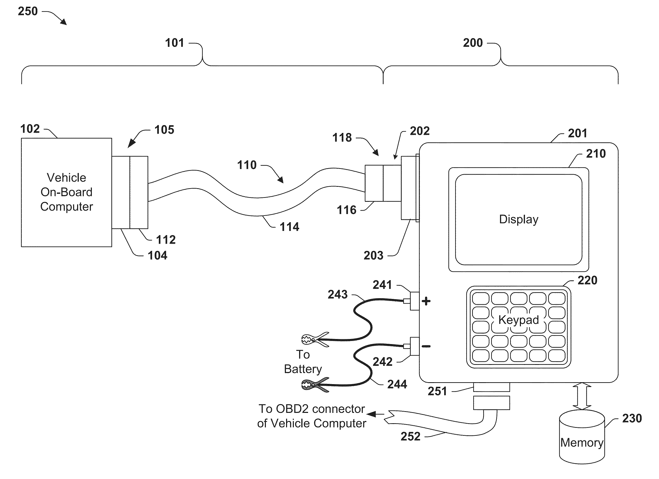
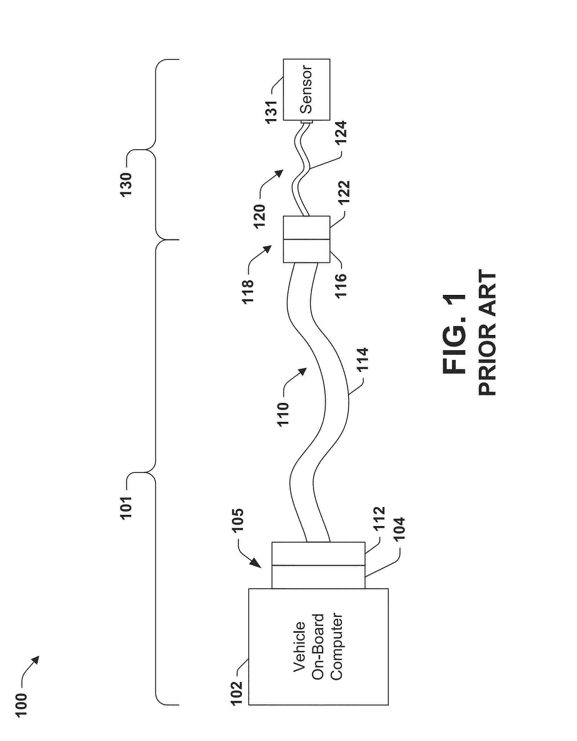
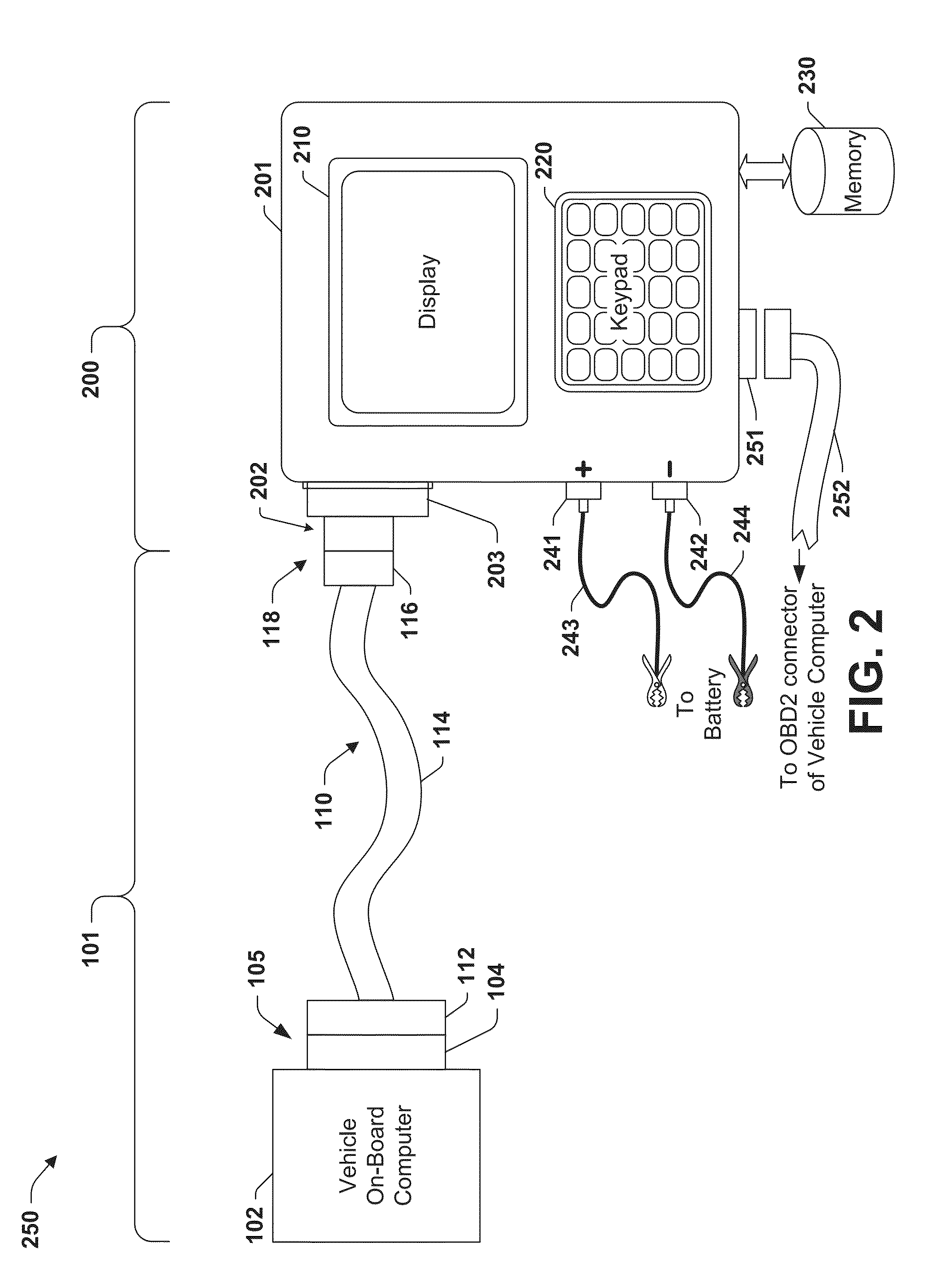
[0027]The present invention will now be described with reference to the attached drawings, wherein like reference numerals are used to refer to like elements throughout. The invention relates to an automotive diagnostic system (ADS) and method for diagnosing problems in a suspect sensor (or sensor system), a vehicle sensor wiring harness and a vehicle computer of a vehicle without any connection to the suspect sensor. In one embodiment, the automotive diagnostic system of the present invention accomplishes this goal during a diagnostic mode, by eliminating the sensor and instead simulating the sensor using an automotive diagnostic system that comprises a sensor simulator configured to be selectively coupled to the vehicle computer by way of the vehicle sensor wiring harness which is directly connected therebetween. In one embodiment, the sensor simulator is adapted to simulate an operation of the sensor system to the vehicle computer, and to physically replace the sensor system.

[002...


PUM


Abstract

A system and method is presented for diagnosing problems in a sensor, a vehicle computer and a vehicle sensor wiring harness. The diagnostic system comprises a sensor simulator configured to be selectively coupled to the vehicle computer via a wiring harness during a diagnostic mode, and to eliminate and simulate a known good sensor to the vehicle computer by way of the vehicle sensor wiring harness directly connected therebetween. The system includes an external computer adapted to selectively couple the sensor simulator to the vehicle computer, and a user keypad and memory to receive and store user commands of a selected manufacturer's make, model, year of vehicle, and the function type of the selected sensor, and to enable the user to select or adjust a typical operational value comprising one or more of a voltage, current or resistance operational range values of the selected sensor.

Description

FIELD OF INVENTION[0001]The present invention relates generally to vehicle diagnostic systems and more particularly to an automotive diagnostic system used for diagnosing sensor, sensor wiring harness and related vehicular system problems independent of any connection means to the suspect sensor.BACKGROUND OF THE INVENTION[0002]Automotive control systems and vehicle sensor systems are employed to sense various environmental and performance related operational conditions in and around the vehicle as well as for providing feedback data from the many actuators, controls and sensors of the vehicle. The operating conditions sensed, and / or the resultant output measurements produced by these sensors systems are usually confined to a predetermined or known operational range of measurement values when they are working properly. In addition, when these vehicle sensors are properly connected to their respective wiring harnesses, and these wiring harnesses are providing adequate continuity, the...

Claims


Application Information

Patent Timeline
Patent Type & Authority Applications(United States)
IPC IPC(8): G01M17/007
CPCG01R31/007G01R31/2829G01R31/2848F02D41/22G01M17/00G07C5/0808
Inventor HARDESTY, CARMEN
Owner HARDESTY CARMEN
Why Eureka
Try Eureka