Fluidised bed pyrolysis apparatus and method

a fluidized bed and pyrolysis technology, which is applied in lighting and heating apparatus, combustible gas purification/modification, and combustion types, etc., can solve the problems of char loss at the expense of pyrolysis, and achieve less enthalpy, increase the superficial gas velocity, and increase the biomass throughput

Active Publication Date: 2014-01-09
UNIVERSITY OF PRETORIA +1
View PDF4 Cites 9 Cited by
  • Summary
  • Abstract
  • Description
  • Claims
  • Application Information

AI Technical Summary

Benefits of technology

[0031]The SGV in the pyrolysis fluidised bed may be from 0.2 to 2 m/s, typically 0.5 m/s. It is believed that in this way less enthalpy is lost by means of heating the cold recycle gas. The bio-mass also enters as a solid, and leaves as a gas, thereby increasing the superficial gas velocity as the pyrolysis reaction occurs. The SGV of the recycled pyrolysis gas is controlled or selected in relation to the degree of entrainment of hot particles in the combustion zone and thus if high entrainment occurs at 2.5 m/s, for instance, a low SGV of recycle pyrolysis gas can be selected in order to allow larger throughput of biomass before SGV gets unacceptably high due to vapourizat...

Problems solved by technology

In order to reduce the electrical energy demand, char produced by the pyrolysis of the bio-mass is recycled as a fuel to the pyrolysis reaction where...

Method used


Image

  • Fluidised bed pyrolysis apparatus and method
  • Fluidised bed pyrolysis apparatus and method
  • Fluidised bed pyrolysis apparatus and method

Examples


Embodiment Construction

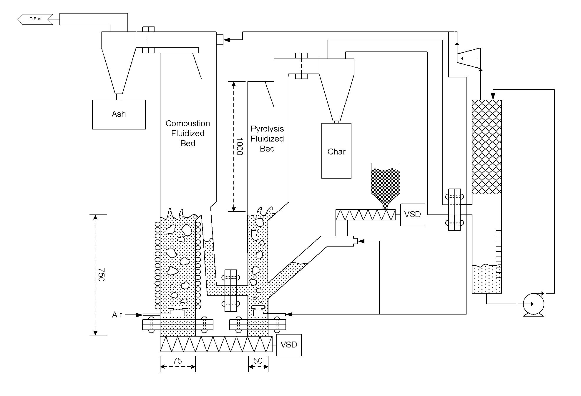
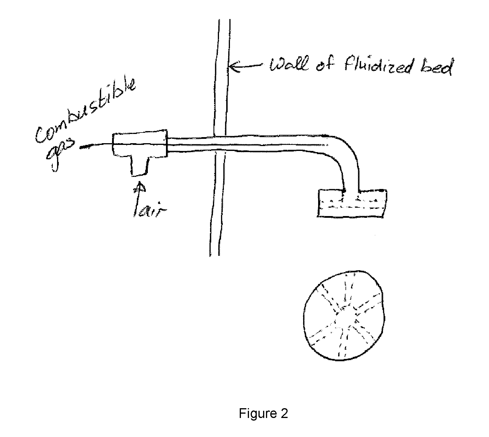
[0039]The invention will now be described, by way of non-limiting example only, with reference to the accompanying flow sheet and diagrammatic drawings, FIGS. 1 and 2.

[0040]In FIG. 1 is shown a dual fluidised bed pyrolysis apparatus of the invention;

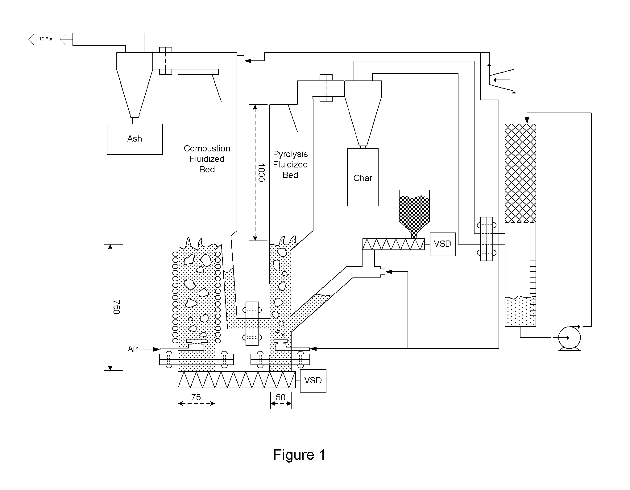
[0041]In FIG. 2 is shown a nozzle arrangement for the fluidised beds of FIG. 1; and

[0042]In FIG. 3 is shown another embodiment of the pyrolysis apparatus of FIG. 1.

[0043]In the flow sheet 10 of FIG. 1, representing an embodiment of this invention, a pyrolysis apparatus 12 and a pyrolysis process is provided for rapidly heating bio-mass to be pyrolysed to bio-oil by mixing it in a pyrolysis fluidised bed 14 with hot particles, in the form of hot sand 16, from a separate fluidised bed operating in combustion conditions.

[0044]The combustion fluidised bed 18 has a cross sectional area 3 to 4 times that of the cross sectional area of the pyrolysis fluidised bed 14.

[0045]In FIG. 1, the combustion fluidised bed 18 is kept hot, typically around ...


PUM


Abstract

A carbonaceous feed pyrolysis apparatus is provided including two or more hot particle fluidised beds, and one or more positive displacement apparatus for the transfer of hot particles between two or more of the beds, wherein one or more of the fluidised beds contains a combustion zone. A bio-oil production process is also provided, including pyrolysis of a carbonaceous bio-mass using two or more fluidized beds, including a first combustion zone carried out in one or more combustion fluidized beds in which a particulate material is fluidized and heated, and a second pyrolysis zone carried out in one or more pyrolysis fluidized beds in which the hot particles heated in the combustion zone are used for pyrolysis of the bio-mass.

Description

FIELD OF THE INVENTION[0001]The invention relates to the pyrolysis of carbonaceous material, such as bio-mass, in a fluidised bed pyrolysis apparatus.BACKGROUND TO THE INVENTION[0002]Fast pyrolysis of bio-mass involves rapidly heating solid bio-mass to a temperature of 400° C. to 600° C. in reducing conditions so that it forms an oil. This is typically done in a fluidized bed, where approximately 60% of the original biomass can be recovered as oil. The pyrolysis is endothermic in nature, and the energy required is typically obtained by heating the fluidized bed indirectly, using electrical heating elements.[0003]The source of heat for heating the fluidised bed is sand which is heated using electrical heating elements to provide the energy for the endothermic reaction. Electrical energy is continuously required in order to maintain the pyrolysis reaction.[0004]In order to reduce the electrical energy demand, char produced by the pyrolysis of the bio-mass is recycled as a fuel to the ...

Claims


Application Information

Patent Timeline
IPC IPC(8): C10B49/22
CPCC10B49/22C10B53/02C10K1/16F23C10/005F23C10/01F23C10/20F23C10/24Y02P20/145Y02P20/129Y02E50/10
Inventor HEYDENRYCH, MICHAEL DAVIDSWART, STEPHEN DAVIDBOATENG, AKWASI ACHEAMPONG
Owner UNIVERSITY OF PRETORIA
Why Eureka
Try Eureka