Calibration and quantification method for gas imaging camera

a gas imaging and quantification method technology, applied in the field of calibration and quantification of gas imaging infrared (ir) cameras, can solve the problems of inability to provide quantitative measurement, adoption of gas imaging technology as a complete replacement, and inability to meet the requirements of different facilities

Active Publication Date: 2014-01-09
PROVIDENCE PHOTONICS
View PDF5 Cites 51 Cited by
  • Summary
  • Abstract
  • Description
  • Claims
  • Application Information

AI Technical Summary

Problems solved by technology

There is no standard across different facilities by which a camera can be deemed to be in good working condition.
A limiting factor for the adoption of gas imaging technology as a complete replacement for conventional methods of leak detection is the inability to provide a quantitative measurement.

Method used


Image

  • Calibration and quantification method for gas imaging camera
  • Calibration and quantification method for gas imaging camera
  • Calibration and quantification method for gas imaging camera

Examples


Embodiment Construction

[0027]The present invention will now be described more completely with reference to the accompanying drawings, in which exemplary embodiments of the invention are shown.

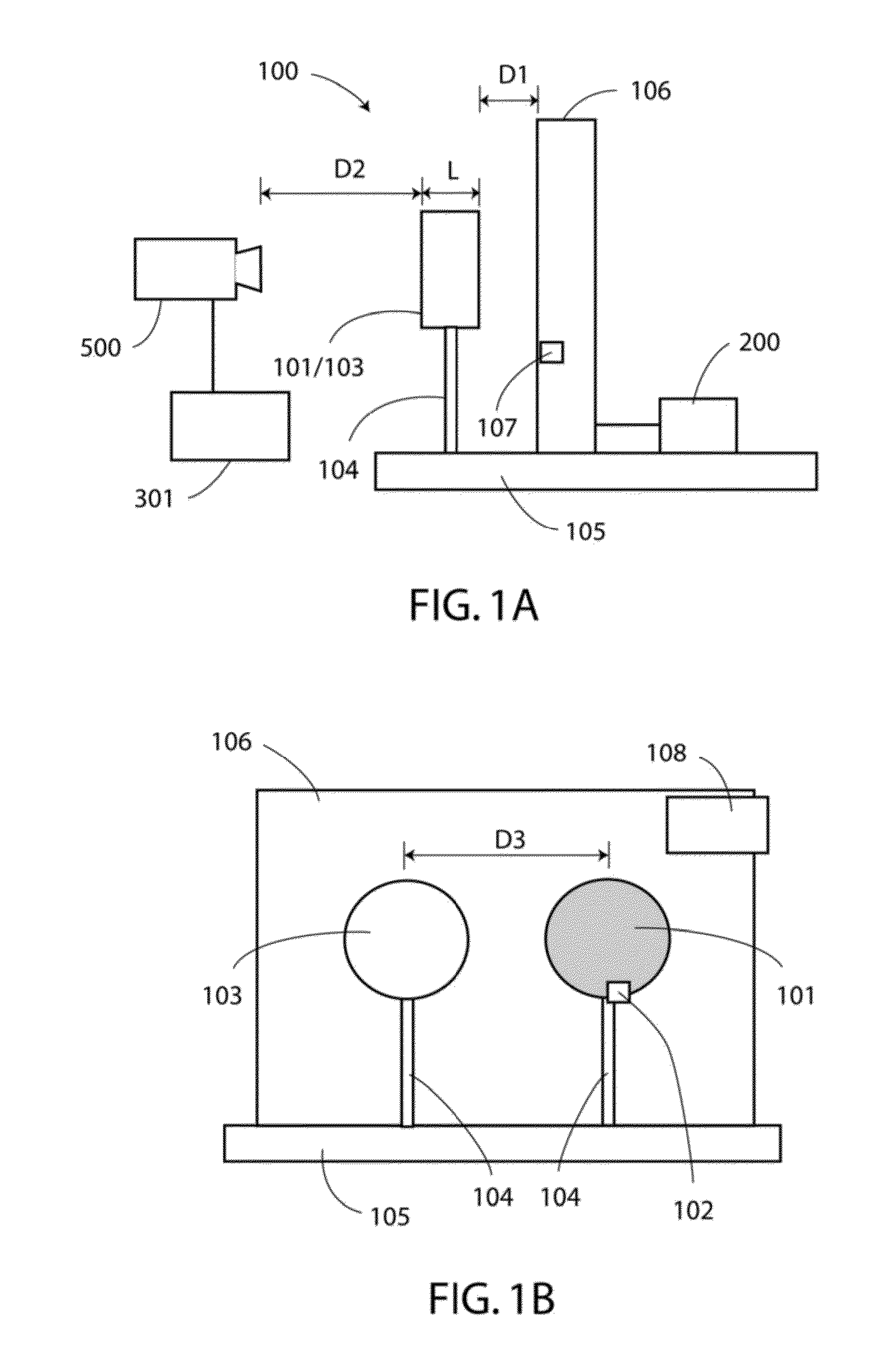
[0028]The verification system 100 for validating or calibrating the performance of a gas imaging infrared (IR) camera is illustrated in FIGS. 1A and 1B. The side view of the verification system 100 is shown in FIG. 1A, and a front view of the verification system 100, viewed from the position of a camera 500, is shown in FIG. 1B. The camera 500 is a gas imaging IR camera to be verified or calibrated. The camera 500 includes any imaging system that is capable of detecting gas leak. The camera 500 may be an infrared imaging system, but is not limited to this type of imaging system.

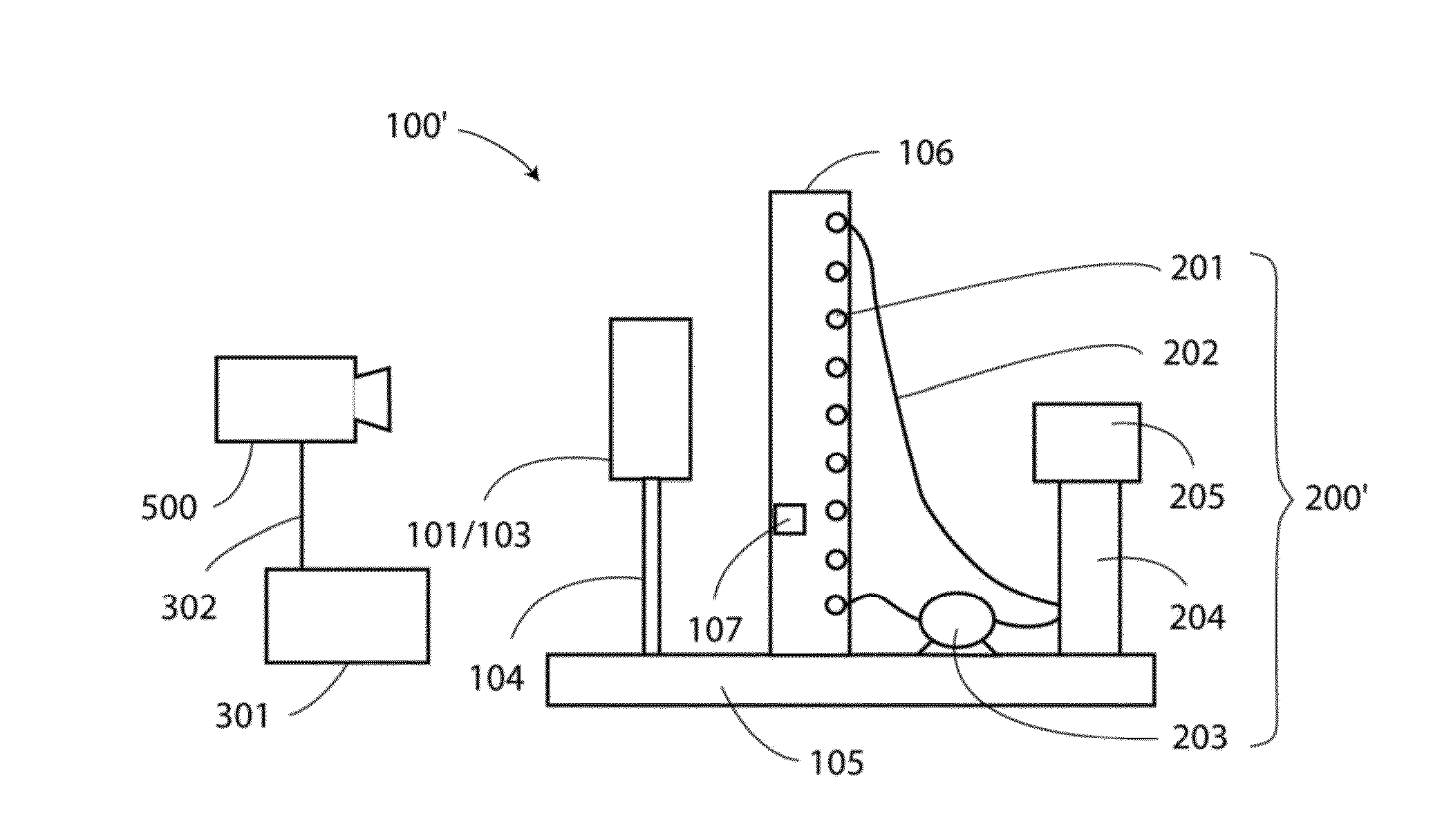
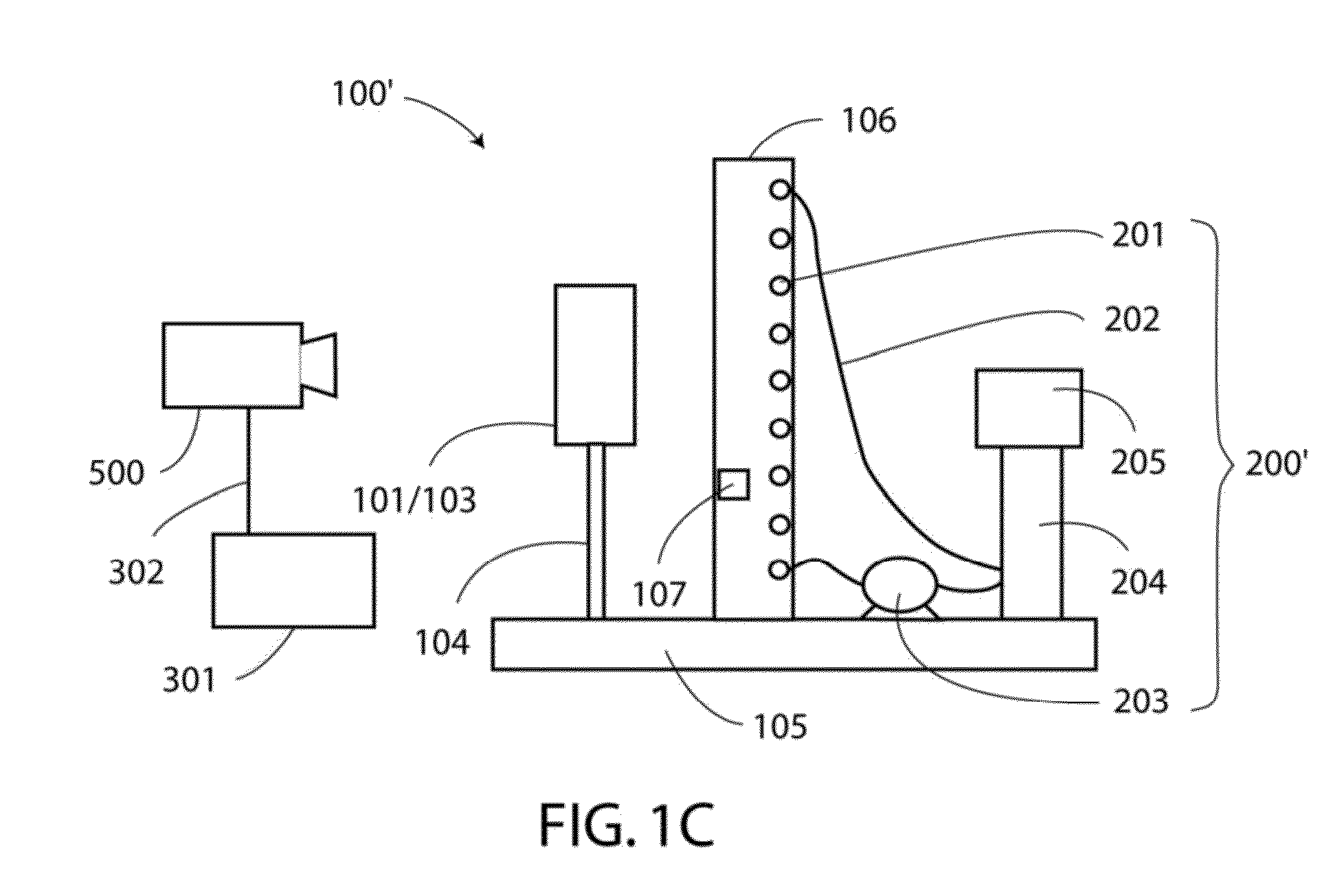
[0029]Referring to FIGS. 1A and 1B, the verification system 100 includes two gas-filled cells 101 and 103, a background board 106, a temperature controlling unit 200 that controls temperature of the background board 106, and a pixel intensity ...


PUM


Abstract

The calibration / verification system and method for gas imaging infrared cameras standardizes the procedures to objectively and consistently check performance of gas imaging infrared cameras. This system includes a background board maintaining a uniform temperature, a target cell filled with a target compound and disposed in front of the background board, a reference cell filled with a reference compound and disposed in front of the background board, and an analyzer coupled to the camera that captures images of the gas cell and the reference cell. The analyzer compares the intensity difference and the temperature difference of rays passing through the target cell and reference cell to a reference relationship data of a quality control chart to determine whether the camera is in a working condition. The method is further extended to provide a quantitative measurement of a hydrocarbon plume from a gas imaging infrared camera.

Description

CLAIM OF PRIORITY[0001]This application claims priority under 35 U.S.C. §119 to Provisional Patent Application No. 61 / 668,781, entitled “CALIBRATION / VERIFICATION DEVICE FOR GAS IMAGING INFRARED CAMERAS” filed on the 6 Jul. 2012, which application is incorporated herein by reference.BACKGROUND OF THE INVENTION[0002]1. Field of the Invention[0003]The present invention relates to a calibration and quantification method for gas imaging infrared (IR) cameras. The calibration and / or verification system and method quantitatively determine the performance of a particular gas imaging IR camera, and determine whether the gas imaging IR camera is in a working condition. The quantification method determines the concentration and / or leak rate observed by a gas imaging IR camera.[0004]2. Description of the Related Art[0005]In recent years, gas imaging Infrared (IR) cameras have become a popular tool in hydrocarbon processing industries for gas leak detection. On Dec. 22, 2008, the U.S. Environmen...

Claims


Application Information

Patent Timeline
Patent Type & Authority Applications(United States)
IPC IPC(8): H04N5/33
CPCH04N5/33G01N21/3504G01N21/274G01N2021/3513G01J5/0014G01J2005/0077G01M3/38G01M3/007G01J5/80G01J5/53
Inventor ZENG, YOUSHENGMORRIS, JON
Owner PROVIDENCE PHOTONICS
Why Eureka
Try Eureka