Llc balancing

a converter arrangement and llc technology, applied in the direction of dc source parallel operation, efficient power electronics conversion, electric variable regulation, etc., can solve the problems of reducing the reliability and practicability of the resulting llc converter arrangement compared to the performance of the original llc converter, and achieve good reliability, practicability and efficiency of the converter arrangement, and overcome the unbalanced loading of its different singles

Active Publication Date: 2014-01-09
DELTA ELECTRONICS (THAILAND) PUBLIC CO LTD
View PDF5 Cites 13 Cited by
  • Summary
  • Abstract
  • Description
  • Claims
  • Application Information

AI Technical Summary

Benefits of technology

[0003]It is the object of the invention to create a converter arrangement pertaining to the technical field initially mentioned, that is able to overcome unbalanced loading of its different single LLC converters while maintaining a good reliability, practicability and efficiency of the converter arrangement.

Problems solved by technology

Unfortunately using common active current sharing methods known from interleaved PWM converters has some major drawbacks for resonant converters and / or LLC converters in parallel connection: The switching frequencies of the paralleled converters would be close to each other but not perfectly the same, resulting in beat frequency effects that can be very critical to EMI requirements and thus afford extensive filtering.
Motivated by those issues, several workarounds to realize load balancing for interleaved LLC converters have been proposed (for example in US 20090231887), but these methods all have the disadvantage of reducing the reliability and practicability of the resulting LLC converter arrangement compared to the performance of the original LLC converter.

Method used


Image

  • Llc balancing
  • Llc balancing
  • Llc balancing

Examples


first embodiment

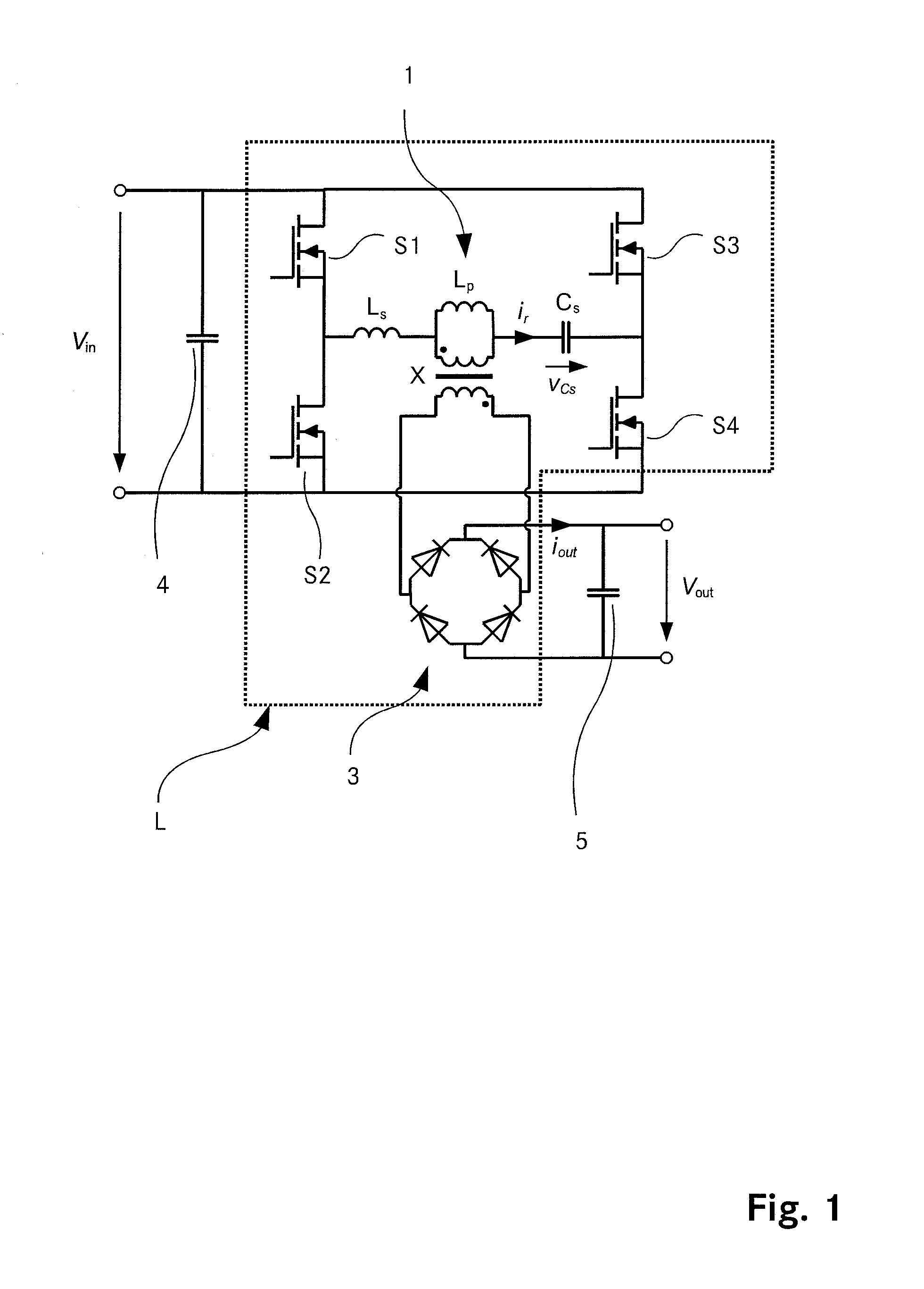
[0065]FIG. 5 now shows a converter arrangement C.5 according to the invention which has the objective to overcome the unbalanced loading at component value mismatch shown in FIG. 4. An active load balancing control 7.5 is added to the control structure 6.5. Its inputs are the measured output currents of the single converters (here: iout—A and iout—B). The load balancing control 7.5 compares the single output currents to each other and takes action in order to balance the loading between the single LLC converters L by either applying more phase-shift (here: φA resp. φB) to the single LLC converter L that is more loaded than the other or applying less phase-shift to the single LLC converter L that is less loaded than the other or by combining both actions. “Applying more phase-shift to the converter” is to be understood as “increasing a switching delay between the switches S1 and S4 (or the switches S2 and S3), at least between the turn-off switching events of the switches S1 and S4 (...

second embodiment

[0067]FIG. 7 shows the invention. The converter arrangement shown here comprises a multi-link input source 8.7 and a control link 9 to this multi-link input source 8.7. The multi-link input source 8.7 is characterized by that it provides two DC voltage links and each of the links is connected to the input voltage of one single LLC converter L (here: Vin—A and Vin—B). Furthermore, it is required that the input voltages supplied by the multi-link input source 8.7 can be adjusted within an appropriate range by using the control link 9. Examples for an applicable multi-link input source are the Vienna-rectifier in case of two interleaved single LLC converters L or multiple single (single phase and / or single rail) PFC rectifiers in case of an arbitrary number of interleaved single LLC converters L or a three-phase Y-rectifier facilitating three (or a multiple of three) independently adjustable input voltages for the single LLC converters L. In FIG. 7, the solution with a Vienna-rectifier...

fourth embodiment

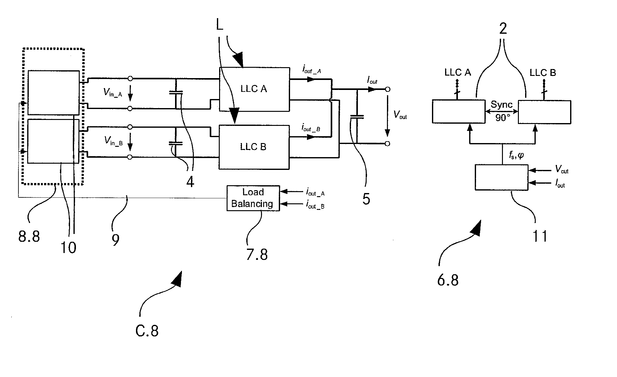
[0068]FIGS. 8 and 9 show a third and the invention, respectively. In FIG. 8, a multi-link power source 8.8 comprising two single PFC rectifiers 10 is used. Each of the PFC rectifiers 10 supplies an input voltage to one single LLC converter L of the converter arrangement C.8. The embodiment shown in FIG. 9 uses a three phase Y-rectifier to supply three input voltages to a converter arrangement C.9 comprising three single LLC converters L.

[0069]FIG. 10 shows switching patterns and waveforms when the load balancing routine characteristic for the second embodiment as shown in FIG. 7 is applied in case of the component value mismatch example used already in FIG. 4. As can be seen at the bottom of FIG. 10, the application of this load balancing routine leads to a considerable load balancing visualized by the homogenized waveforms the currents A.iout, and B.iout.


PUM


Abstract

A converter arrangement (C.5, C.7, C.8, C.9, C.11, C.12) with at least two single LLC converters (L), a pulse generator (2) per single LLC converter (L) wherein each pulse generator (2) is configured to supply switching pulses to one single LLC converter (L) and an output controller (11) configured to use switching frequency control and/or phase-shift control to control the pulse generators (2) comprises a load balancing control (7.5, 7.7, 7.8, 7.9, 7.11, 7.12) for overcoming unbalanced loading of the converter arrangement (C.5, C.7, C.8, C.9, C.11, C.12).

Description

TECHNICAL FIELD[0001]The invention relates to a converter arrangement comprising at least two single LLC converters, one pulse generator per single LLC converter, wherein each pulse generator is configured to supply switching pulses to one single LLC converter, and an output controller configured to use switching frequency control and / or phase-shift control to control the pulse generators. In further, the invention relates to a method for operating said converter arrangements.BACKGROUND ART[0002]LLC resonant converters are more and more used in modern power supply designs due to their ability to operate with high efficiency at moderate circuit and control complexity. Moreover, the interleaving method, i.e. combining multiple single LLC resonant converters, in particular in parallel connections, is commonly used in modern power supply designs to increase the maximum output power per unit, to spread power losses, to apply phase shedding in light load operation and to decrease the size...

Claims


Application Information

Patent Timeline
Patent Type & Authority Applications(United States)
IPC IPC(8): H02M3/158
CPCH02M3/1584H02M3/28H02M3/285Y02B70/10H02M3/33573H02M3/01H02J1/102H02M7/4815
Inventor FIGGE, HEIKOSCHAFMEISTER, FRANKGROTE, TOBIAS
Owner DELTA ELECTRONICS (THAILAND) PUBLIC CO LTD
Why Eureka
Try Eureka