Plasma coating device and method for plasma coating of a substrate

Inactive Publication Date: 2014-01-09
MASCHFAB REINHAUSEN GEBR SCHEUBECK GMBH & CO KG
View PDF6 Cites 1 Cited by
  • Summary
  • Abstract
  • Description
  • Claims
  • Application Information

AI Technical Summary

Benefits of technology

The present invention provides a plasma coating device and method that allows for the conveying of a powder or mixture of powder and processing gas from a powder reservoir into a processing chamber while ensuring a homogeneous, precise, pulsation-free, and stable powder conveyance. The device achieves this without the need for a pumping unit in the powder transport line, which eliminates the possibility of mechanical or pneumatic units interfering with the powder conveyance. The invention results in a more efficient and controlled plasma coating process.

Problems solved by technology

The conveyance of such fine-grained powders is, however, challenging.
Furthermore, fine-grained powders tend to form agglomerates that a processing gas stream may not be able to break up.
Also, the operation of suitable types of pumps often becomes unstable when handling processing gases with high powder contents.
Pumps and conveyance devices are prone to heavy erosion and blockage depending on the powder used.
Also, the properties of the powder material itself have a significant impact.
This process is, however, very complex and not sufficiently reliable for powders prone to agglomeration.
Likewise, the problem remains unaddressed of how a constant extraction rate of deposition material is achieved.

Method used


Image

  • Plasma coating device and method for plasma coating of a substrate
  • Plasma coating device and method for plasma coating of a substrate
  • Plasma coating device and method for plasma coating of a substrate

Examples


Embodiment Construction

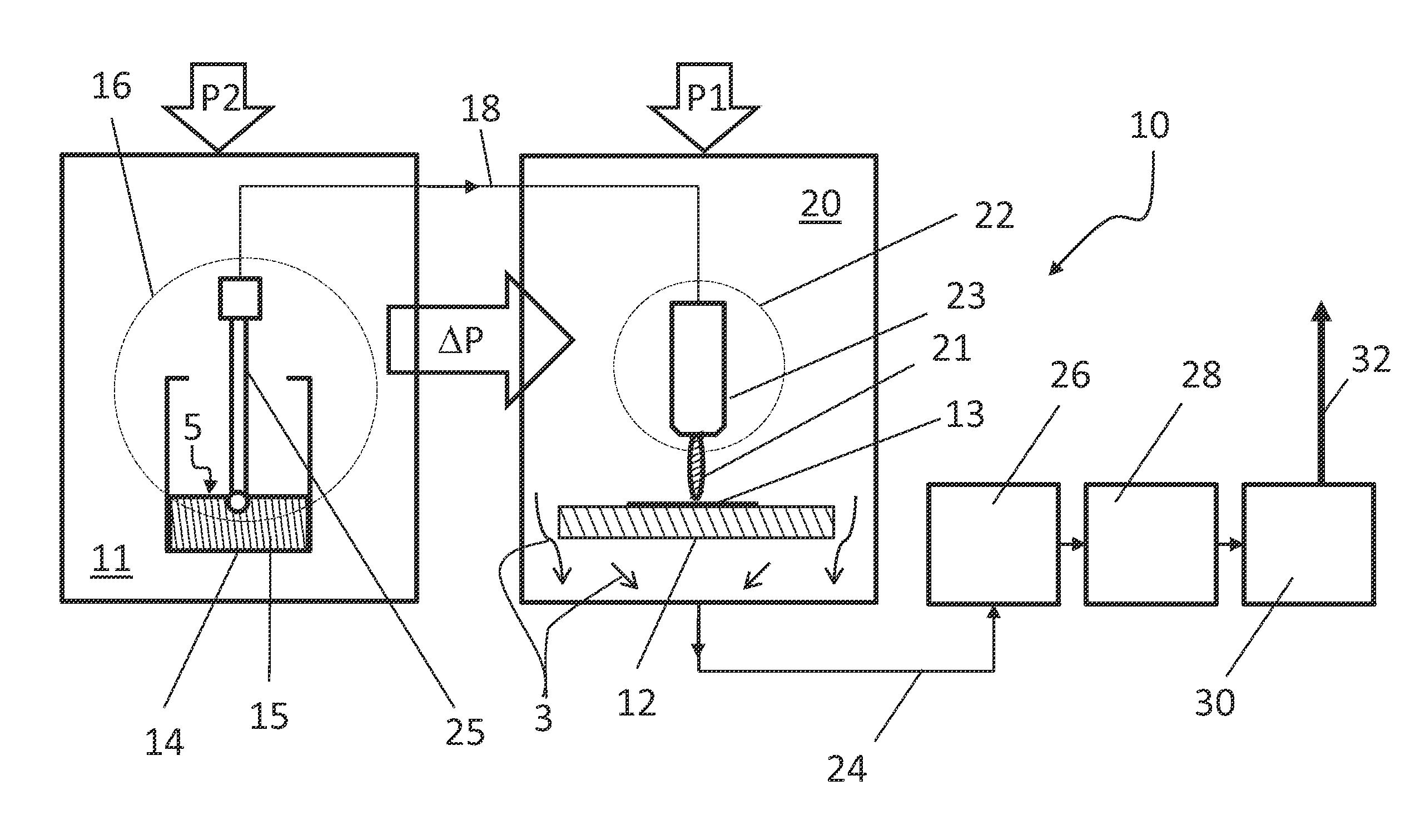
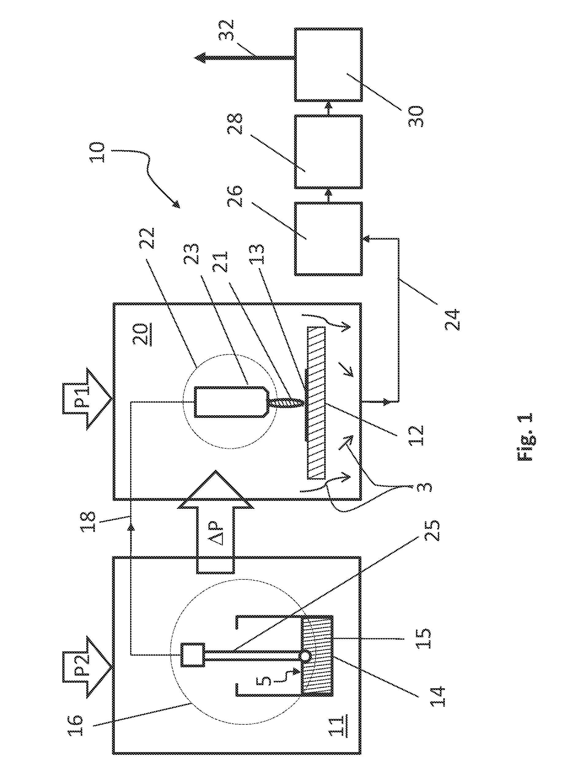
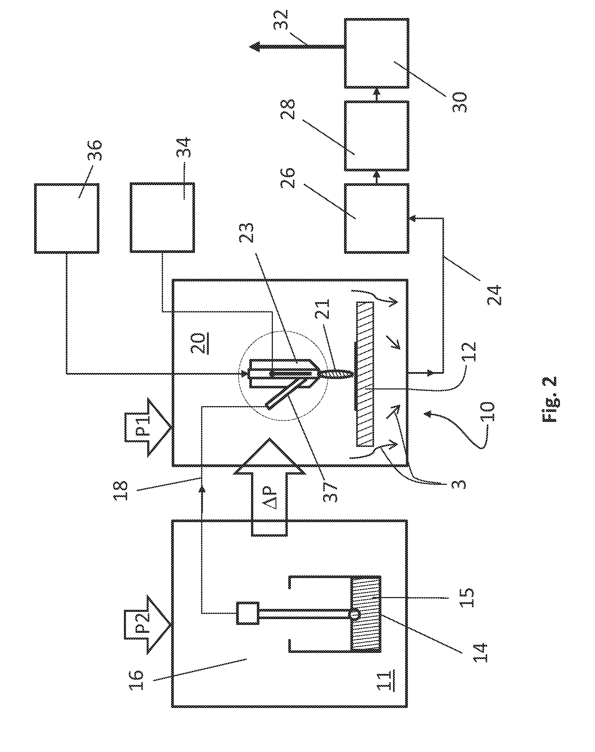
[0026]At the outset, it should be appreciated that like drawing numbers on different drawing views identify identical, or functionally similar, structural elements of the invention.

[0027]While the present invention is described with respect to what is presently considered to be the preferred aspects, it is to be understood that the invention as claimed is not limited to the disclosed aspect. The present invention is intended to include various modifications and equivalent arrangements within the spirit and scope of the appended claims.

[0028]Furthermore, it is understood that this invention is not limited to the particular methodology, materials and modifications described and as such may, of course, vary. It is also understood that the terminology used herein is for the purpose of describing particular aspects only, and is not intended to limit the scope of the present invention, which is limited only by the appended claims.

[0029]Unless defined otherwise, all technical and scientifi...


PUM

PropertyMeasurementUnit
Pressureaaaaaaaaaa
Pressureaaaaaaaaaa
Pressureaaaaaaaaaa

Abstract

The invention relates to a plasma coating device (10) and a method for homogenous coating of a substrate (12). It comprises a particle reservoir (14), a dosing device (16) for dosing the particles (15) contained in the particle reservoir (14), a processing chamber (20) and a transport line (18) to convey particles (15) into the processing chamber (20). The processing chamber pressure (P1) in the processing chamber (20) is lower than the particle reservoir pressure (P2) in the particle reservoir (14).

Description

CROSS-REFERENCE TO RELATED APPLICATIONS[0001]This application claims priority from German Patent Application No. 10 2012 106 078.2, filed on Jul. 6, 2012, which application is incorporated herein by reference in its entirety.FIELD OF THE INVENTION[0002]The invention relates generally to a plasma coating device, and more specifically to a plasma coating device for coating of a substrate.[0003]Furthermore, the invention generally relates to a method for plasma coating of a substrate.BACKGROUND OF THE INVENTION[0004]The state of the art comprises a diverse series of sample coating methods and devices. The methods may be selected according to the substrate, the layer to be coated thereon and in particular according to the layer thickness. Amongst suitable coating methods are, according to the initial state of the coating material, gas-phase deposition, dip coating, spraying methods, electroplating or powder coating. Some methods, amongst which in particular thermal spraying methods, pla...

Claims


Application Information

Patent Timeline
IPC IPC(8): C23C4/12
CPCC23C4/127C23C16/4486C23C16/513B05B7/1472B05B7/226C23C4/134B05B14/43
Inventor NETTESHEIM, STEFAN
Owner MASCHFAB REINHAUSEN GEBR SCHEUBECK GMBH & CO KG
Why Eureka
Try Eureka