Liquid cooled high efficiency permanent magnet machine with in slot glycol cooling

Active Publication Date: 2014-01-16
LC ADVANCED MOTOR TECH CORP
View PDF30 Cites 9 Cited by
  • Summary
  • Abstract
  • Description
  • Claims
  • Application Information

AI Technical Summary

Benefits of technology

This patent describes a machine that uses a novel stator construction method. The machine uses a cooling system that allows for efficient cooling of both the winding and stator laminations. The design uses high-reliability metallic vessels that are brazed together to efficiently direct the cooling medium to where it is needed. The winding technique utilizes Layer Form Winding, which combines the benefits of traditional form winding with a lower cost manufacturing method that ensures optimal placement of conductors to minimize potential difference between them. This results in a reliable and efficient design that is cost-effective to manufacture.

Problems solved by technology

This design cools the stator better than air, but is limited by i) the conductivity between the jacket and the stator, ii) the poor conductivity of the stator laminations, iii) the conductivity of the slot liners, and iv) the poor conductivity between the winding and the slot liners.
Either of these has similar disadvantages to the cooling jacket design.
These have the disadvantage of either being complex or having the fluid cause drag between the rotor and the stator.
This has the disadvantage of requiring a special fluid and some complex manufacturing methods to provide the fluid channel.
These windings typically require some relatively complex end turns to wire them properly.
This also has complicated end turns and has the disadvantage of being less efficient.
This is the easiest method of stator winding, but results in the lowest amount of conductor in the slot and therefore the lowest efficiency.
This is the most labor-intensive type of winding and is typically used in machines that are less cost sensitive.
This is not typically used for stator windings because it is not typical to be able to bobbin wind a coil and then insert it into a stator assembly.

Method used


Image

  • Liquid cooled high efficiency permanent magnet machine with in slot glycol cooling
  • Liquid cooled high efficiency permanent magnet machine with in slot glycol cooling
  • Liquid cooled high efficiency permanent magnet machine with in slot glycol cooling

Examples


Embodiment Construction

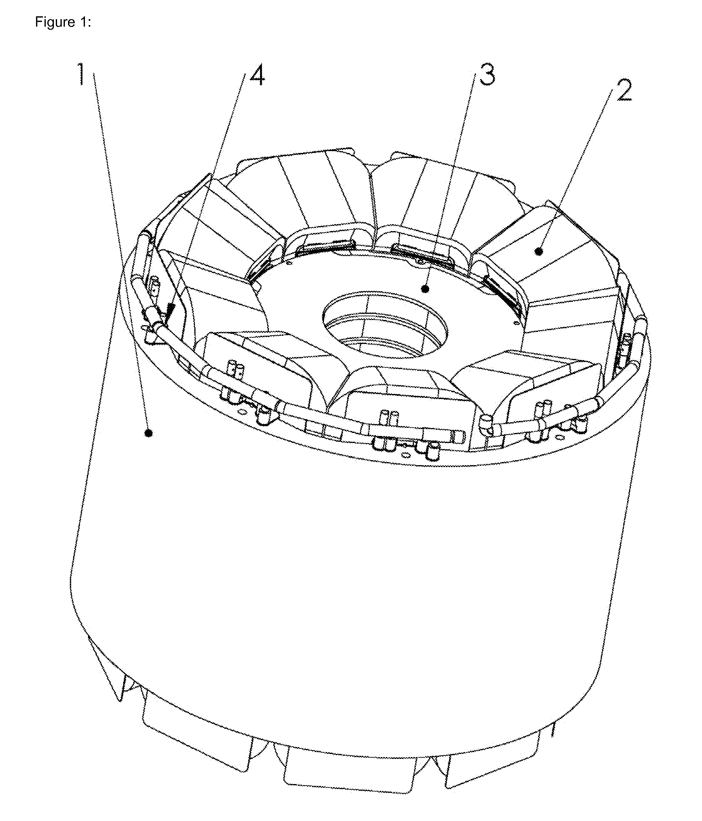
[0031]Referring particularly to FIG. 1, a rotor 3 is shown surrounded by a stator lamination 1 and stator coils 2. Also shown is a fluid manifold 4 for supplying coolant to the motor or generator.

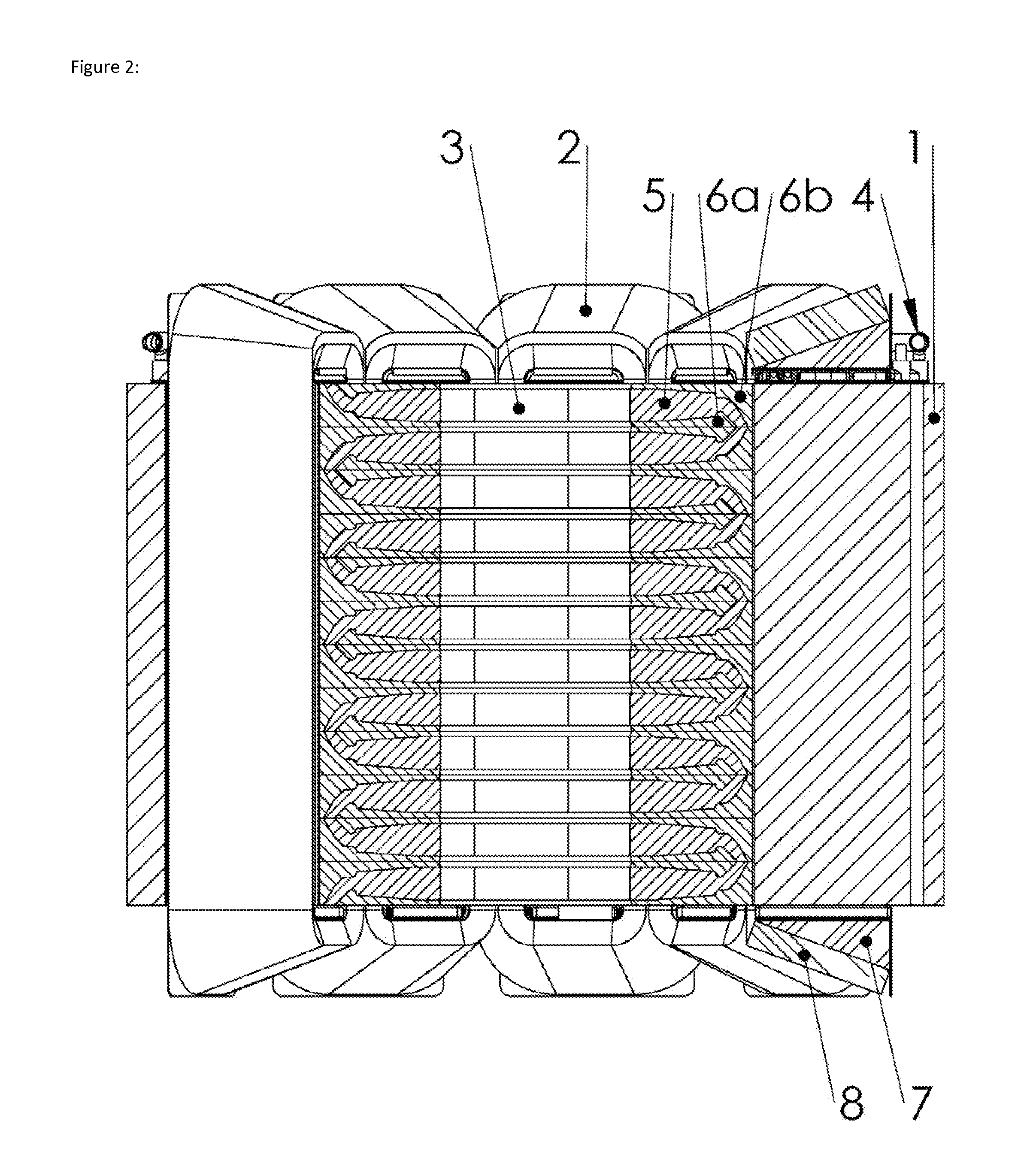
[0032]FIG. 2 shows more detail on the rotor configuration showing magnets 5 and tab pole plates 6a and 6b. This rotor configuration is the same as shown in the two patent applications Ser. No. 13 / 438,792 and Ser. No. 13 / 438,803 filed on Apr. 3, 2012, and each incorporated herein by reference.

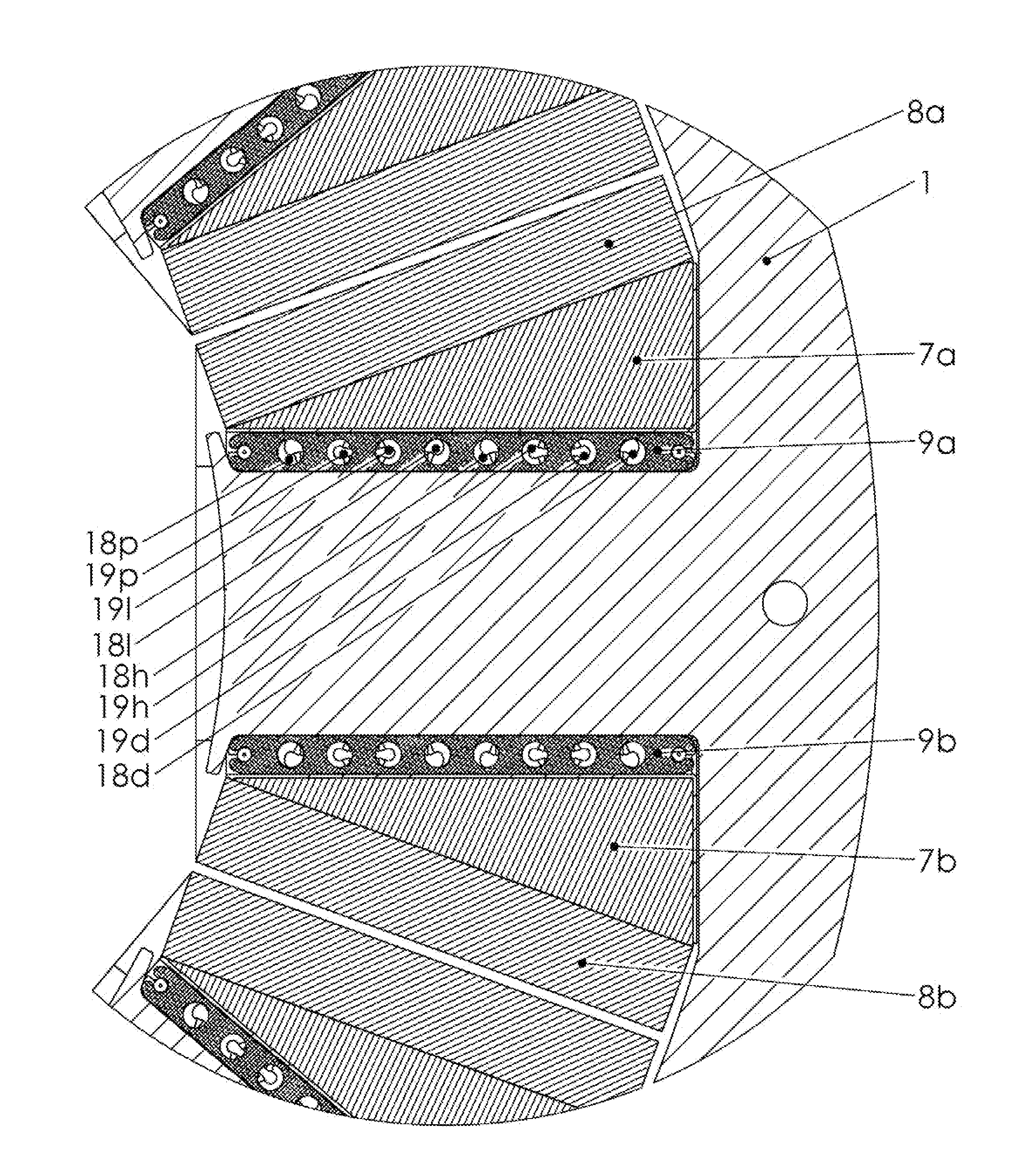
[0033]The stator shown in FIG. 3 has a double layer concentrated winding since there is a winding around every stator tooth. In addition, the stator winding has an inner portion 7 and an outer portion 8 as shown in FIG. 3 and FIG. 4. The inner and outer portions are separate and distinct from this being a double layer winding which refers to there being a winding around every stator tooth.

[0034]The winding surrounds a cooling manifold 9 as shown in FIG. 4. There are 2 redundant coolant loops denoted as ...


PUM


Abstract

A permanent magnet motor, generator or the like that is liquid cooled using glycol or similar fluid with the means defining cooling passageways disposed directly in the winding slots of the stator between and in engagement with the windings and stator laminations.

Description

BACKGROUND OF THE INVENTION[0001]Rotary electric machines including electric motors, generators, and the like have employed various cooling methods including air cooling and liquid cooling. Liquid cooling is used to help make motors smaller and to remove the heat more efficiently.[0002]The most common liquid cooling design uses a cooling jacket wrapped around the outside of the stator assembly. This can be seen in U.S. Pat. No. 5,448,118, included herein by reference. In this design there is an aluminum extrusion that surrounds the outside of the stator and has passages for cooling fluid to pass through. This design cools the stator better than air, but is limited by i) the conductivity between the jacket and the stator, ii) the poor conductivity of the stator laminations, iii) the conductivity of the slot liners, and iv) the poor conductivity between the winding and the slot liners.[0003]Another method that is commonly used is passing cooling through the stator laminations or into ...

Claims


Application Information

Patent Timeline
IPC IPC(8): H02K3/24H02K3/30
CPCH02K3/24H02K3/30H02K9/227H02K9/197
Inventor MARVIN, RUSSEL HUGHJOHNSON, THOMAS R.
Owner LC ADVANCED MOTOR TECH CORP
Why Eureka
Try Eureka