
Wavelength selective optical switch device and method of controlling characteristics thereof

Active Publication Date: 2014-01-16
SANTEC
View PDF9 Cites 10 Cited by
  • Summary
  • Abstract
  • Description
  • Claims
  • Application Information

AI Technical Summary

Benefits of technology

The present invention allows for the reflection or transmission of light beams in multiple directions using a combination of patterns on a region made up of pixels. This optical switch device can select wavelengths with high precision and control them effectively. Additionally, narrowing of wavelengths beyond the designed band is alleviated without generating a fringe effect. The invention also allows for high-resolution attenuation of light of a selected wavelength, and outputting each region's output as an average.

Problems solved by technology

Meanwhile, optical networks have become more complicated with advancements in research and development in accelerating transmission rates and new modulation formats in response to demand for transmission capacity in recent years.

Method used


Image

  • Wavelength selective optical switch device and method of controlling characteristics thereof
  • Wavelength selective optical switch device and method of controlling characteristics thereof
  • Wavelength selective optical switch device and method of controlling characteristics thereof

Examples


first embodiment

[0050]FIG. 7A is a side view as viewed from the x-axis direction illustrating a configuration of an optical element of a reflective type wavelength selective optical switch device according to a first embodiment of the present invention, and FIG. 7B is a side view as viewed from the y-axis thereof. The incident light is a WDM signal beam in which optical signals of wavelengths between λ1 to λn have been multiplexed. The WDM light exits to a collimate lens 12 via respective optical fiber 11. Although the collimate lens 12 outputs beams having fixed widths in the x direction and y direction in parallel, only the center line thereof is illustrated in FIG. 7A. Further, beams that entered into collimate lenses 13-1 to 13-m exit to the outside from optical fiber 14-1 to 14-m arranged in parallel to the respective optical fiber 11. Here, m is a natural number not less than 1. The WDM light that exits from the collimate lens 12 is parallel to the z axis, and the WDM light enters into a wave...

second embodiment

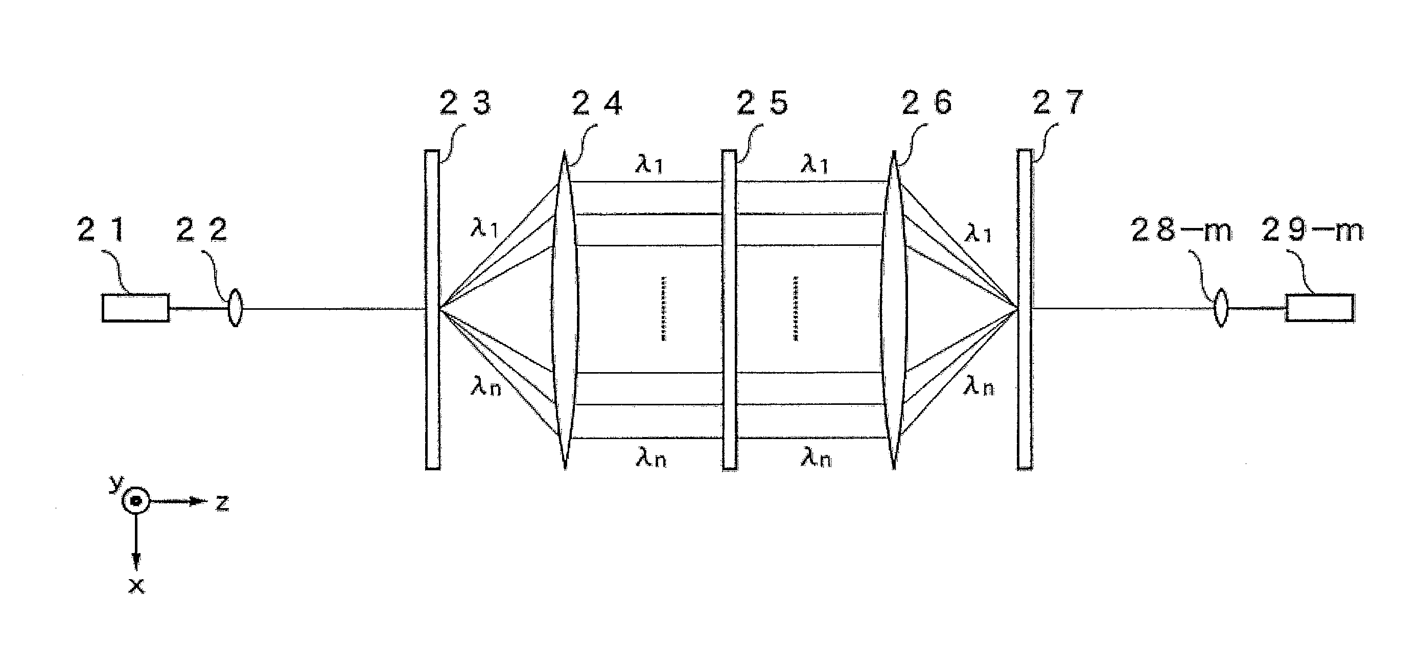
[0052]Next, a description will be given of a transmissive type wavelength selective optical switch device according to a second embodiment of the present invention. FIG. 8A is a side view as viewed from the x-axis direction illustrating a configuration of an optical element of a transmissive type of wavelength selective optical switch device according to a second embodiment of the present invention, and FIG. 8B is a side view as viewed from the y-axis thereof. The incident light in FIG. 8A is also a WDM signal as described in the first embodiment, and it enters the collimate lens 22 from the optical fiber 21 and is provided to the first wavelength dispersion element 23 as a parallel optical beam. The optical fiber 21 and the collimate lens 22 are provided with incident parts where the WDM signal beam enters. The wavelength dispersion element 23 exits light beams in different directions on an xz plane according to the wavelengths of the beams as illustrated in FIG. 8B. The wavelength...


PUM


Abstract

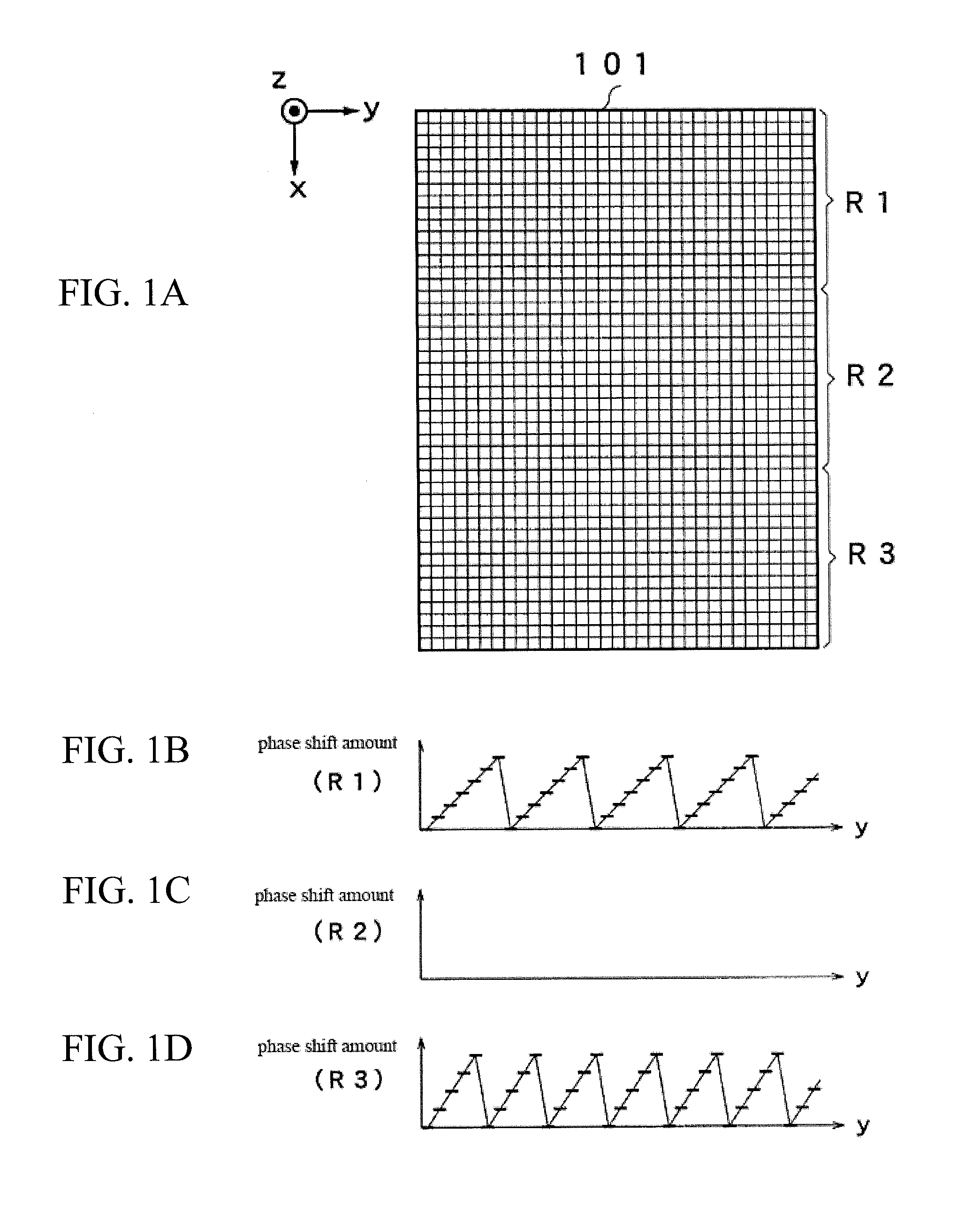
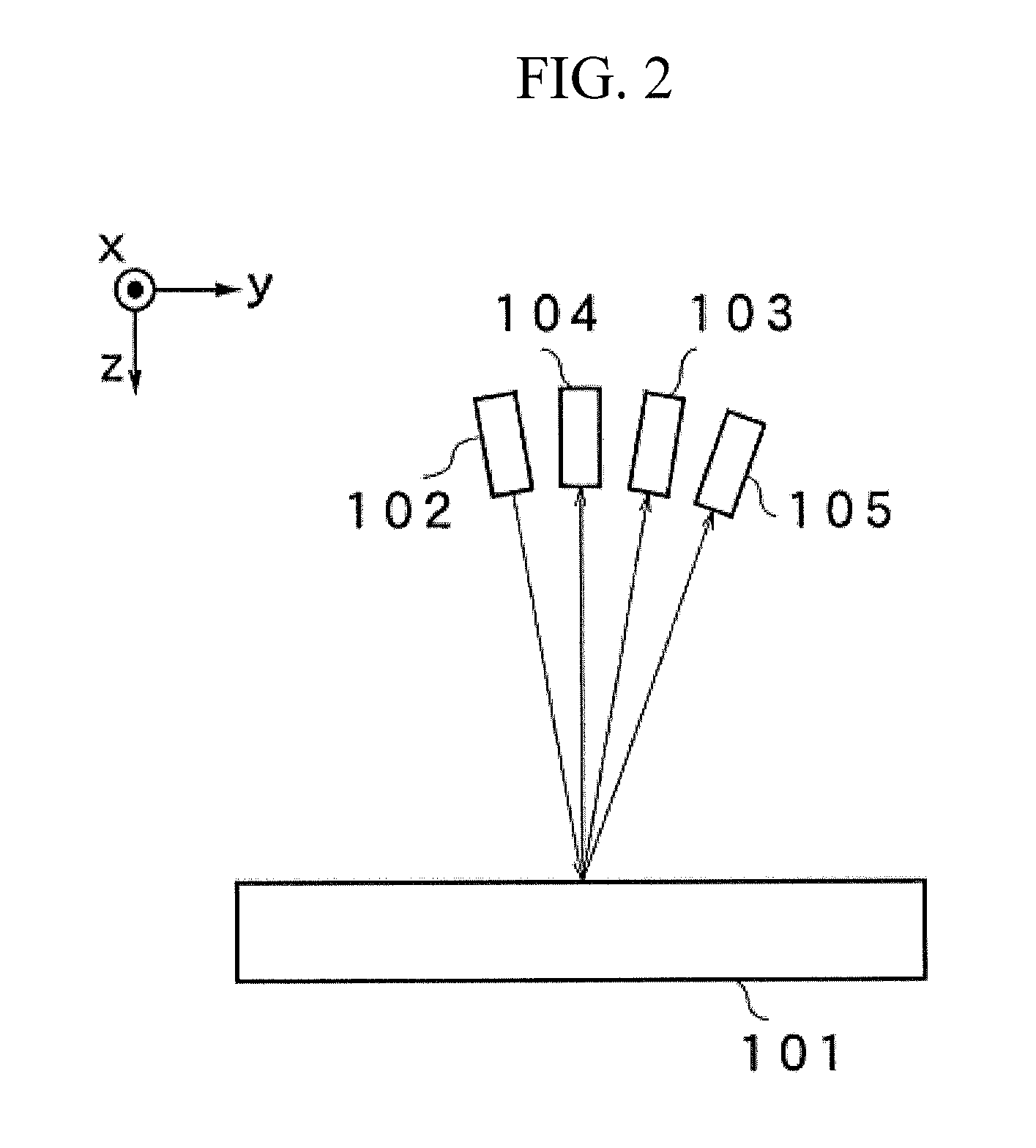
A wavelength selective optical switch device includes an incidence and exit part where a signal beam made of light of a multiplicity of wavelengths enters and a signal beam of a selected wavelength exits, a wavelength dispersion element that spatially disperses a signal beam according to the wavelength thereof and multiplexes reflected light, a condensing element that condenses the light dispersed by the wavelength dispersion element onto a two-dimensional plane, and a wavelength selection element that uses a multilevel optical phased array arranged in a position to receive incident light developed on an xy-plane made of an x-axis direction and a y-axis direction perpendicular thereto developed according to a wavelength, having a multiplicity of pixels arrayed in a lattice on the xy-plane, and that cyclically changes the phase shift amount in the y-axis direction to a sawtooth wave pattern for each pixel on the x-axis.

Description

FIELD OF THE INVENTION[0001]The present invention relates to a wavelength selective optical switch device used in a node or the like of an optical communication system, and a method for controlling characteristics thereofDESCRIPTION OF THE RELATED ART[0002]In high speed large capacity optical networks that support today's advanced information and communication firms, wavelength multiplexing optical communication technology is used. Reconfigurable optical add drop multiplexers (ROADM) that provide reconfigurable add drop functionality are being introduced into optical nodes that correspond to branching points of an optical network. Wavelength selective switches (also referred to as WSS) that switch any wavelength to any direction are garnering attention in the implementation of ROADM devices. An optical beam deflection element is used in wavelength selective switches to select a wavelength that deflects an optical beam to a desired output port. Patent Documents 1 and 2 propose using ...

Claims


Application Information

Patent Timeline
IPC IPC(8): G02F1/29
CPCG02F1/2955G02B26/0833G02F2203/05H04Q11/0005H04Q2011/0016H04Q2011/0026
Inventor HOTTA, YUJI
Owner SANTEC
Learn More