Optical member and method for producing same

a technology of optical components and optical components, applied in the field of optical components, can solve the problems of poor film adhesion and coating properties on structures on which liquid readily collects, incompatibility with the conventional method of laminating oxide thin films used for lenses, and inconvenient production, etc., to achieve high film adhesion, easy formation, and easy control of film thickness

Active Publication Date: 2014-01-16
FUJIFILM CORP
View PDF3 Cites 23 Cited by
  • Summary
  • Abstract
  • Description
  • Claims
  • Application Information

AI Technical Summary

Benefits of technology

[0011]According to the present invention, the problems seen in the conventional methods can be solved and it is possible to provide an optical member which has an antireflection effect on its entire surface or a certain part of its surface even when a substrate having an at least partially curved surface is used. Also, it is possible to provide a method for producing the optical member, whereby a thickness of a film can be easily controlled, high film adhesion is achieved, a film can be easily formed on a structure which is incompatible with a liquid phase reaction such as a substrate having an at least partially curved surface, and at least one of aluminum and alumina can be deposited after forming a dielectric layer by gas-phase deposition without breaking vacuum.

Problems solved by technology

However, the disclosed optical member employs a liquid-phase film forming method (sol-gel method) as a method for forming the fine concavity and convexity, and such method is incompatible with a method for laminating the oxide thin film conventionally used for a lens.
Furthermore, there are problems in that film adhesion and coating properties on a structure on which liquid readily collects, such as a concavity, are poor.
However, Japanese Patent Application Publication (JP-B) No. 61-48124 does not disclose techniques of employing a lens having a curvature as the substrate and forming a dielectric layer between the substrate and the fine concave-convex structure.

Method used


Image

  • Optical member and method for producing same
  • Optical member and method for producing same
  • Optical member and method for producing same

Examples


example 1

Production of Optical Member

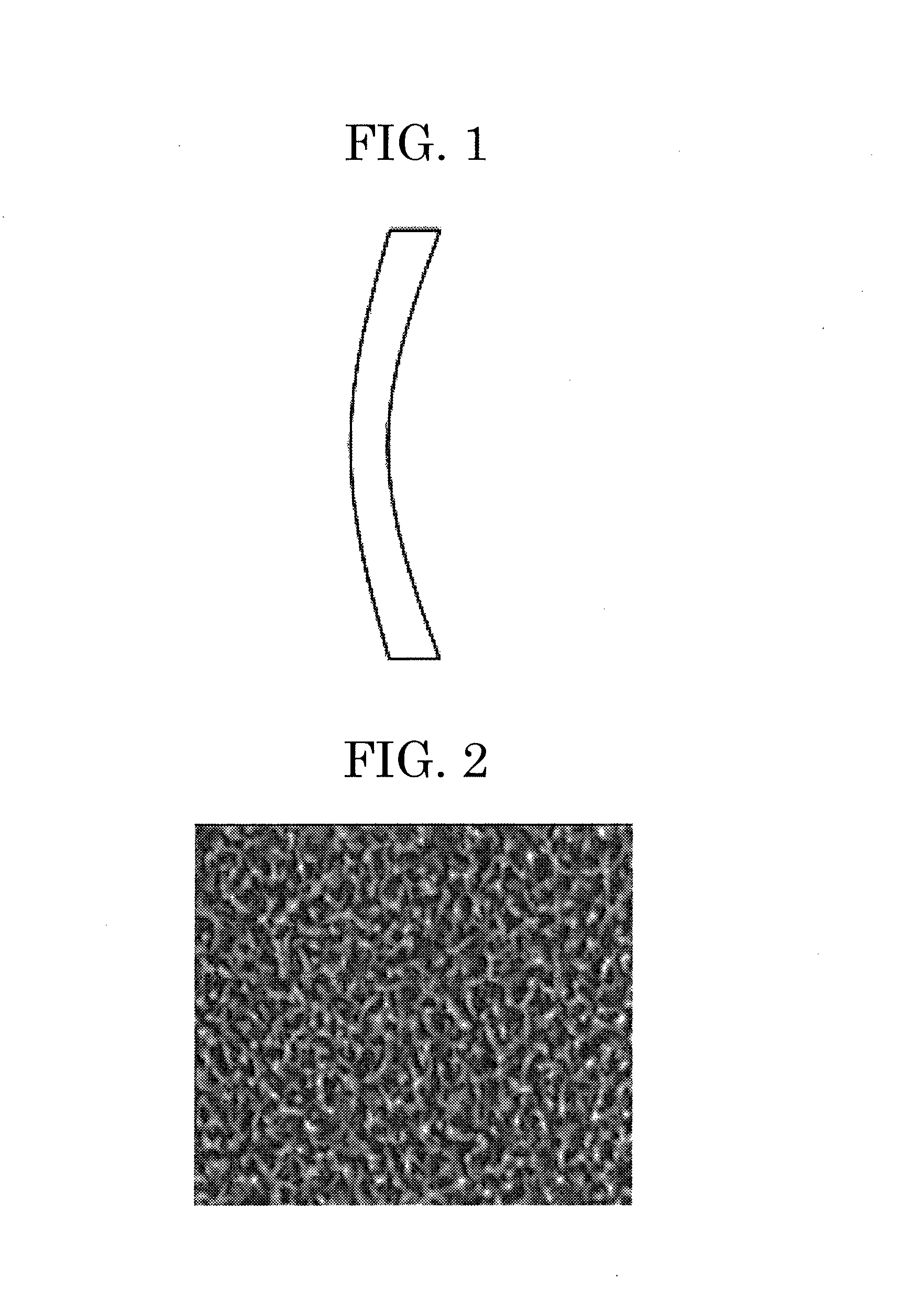
[0073]As a substrate, a concave meniscus lens (material S-TIH6, manufactured by OHARA INC.) shown in FIG. 1 was used. The concave meniscus lens employed a glass having a refractive index for d-line of 1.805.

[0074]The concave meniscus lens was subjected to ultrasonic cleaning using pure water (45 kHz, for 3 minutes), and then, dried by a spin dryer and baking at 150° C.

[0075]Next, the concave meniscus lens was placed at an EB deposition apparatus (manufactured by ULVAC, Inc., EBX-8) so that deposition was conducted on the concave surface of the lens. Vacuuming was carried out up to a vacuum degree of 2.0×10⁻⁶ Torr.

[0076]Next, aluminum oxide was deposited by electron beam vapor deposition using a crystal oscillator as a guide so that the thickness was 58 nm.

[0077]Next, metal aluminum was deposited thereon so that the thickness was 5 nm.

[0078]Next, the concave meniscus lens was placed at the EB deposition apparatus (manufactured by ULVAC, Inc., EBX-8) so tha...

example 2

[0088]An optical member of Example 2 was produced by the same procedure as that in Example 1 except that SiO2 was deposited so that the thickness was 53 nm instead of depositing aluminum oxide so that the thickness was 58 nm in Example 1.

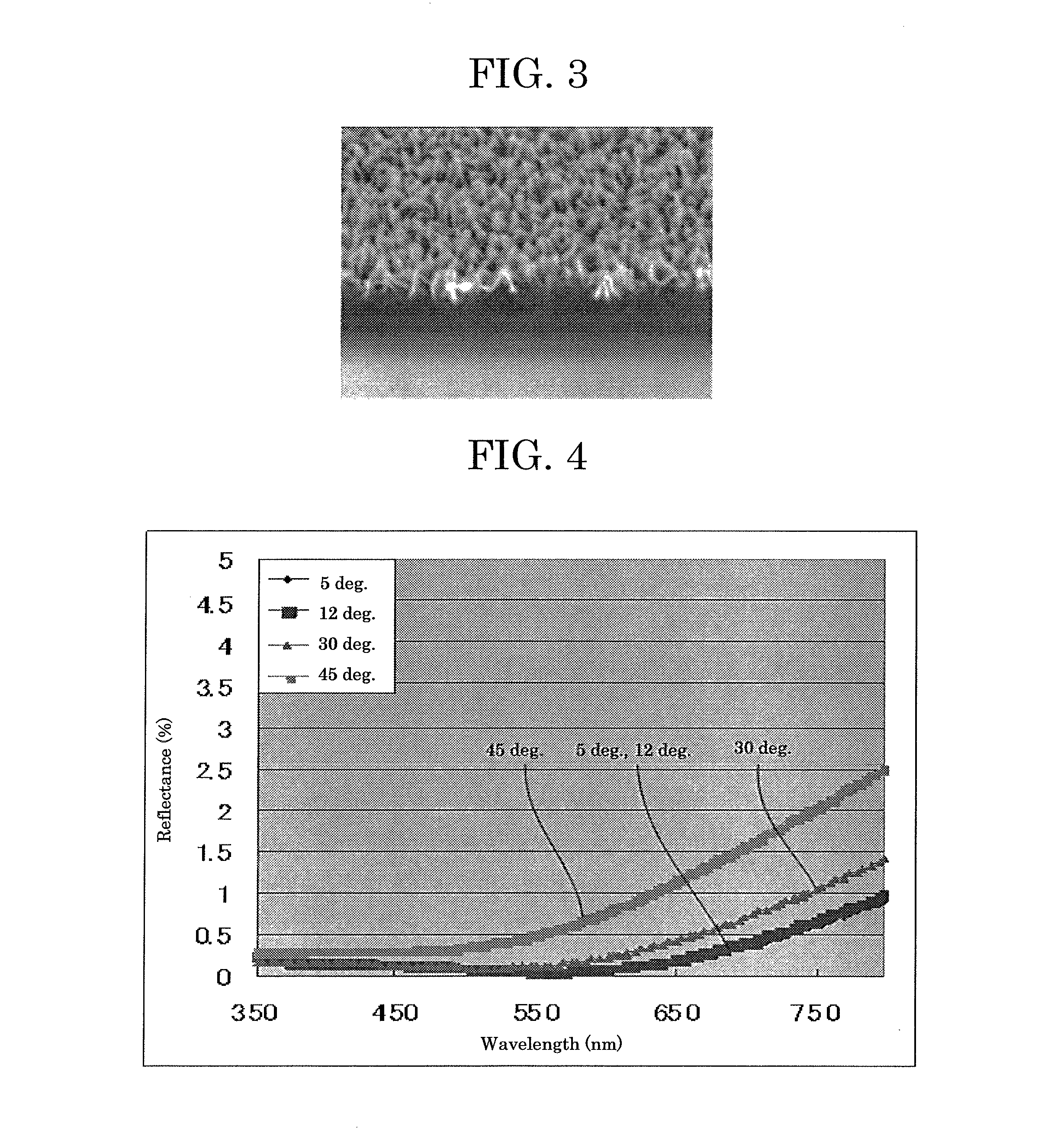
[0089]FIG. 5 shows spectral reflectances of the obtained optical member. Measurement was performed for the reflectances on front and back surfaces. FIG. 5 shows reflectances at incident angles of 5 degrees, 12 degrees, 30 degrees, and 45 degrees. Further, Table 2 shows average reflectances for light ranging from 380 nm to 780 nm at incident angles of 5 degrees, 12 degrees, 30 degrees, and 45 degrees.

TABLE 2Incident angleVisible light average reflectance (%) 5 degrees0.4012 degrees0.4230 degrees0.5945 degrees1.19

[0090]FIG. 5 and Table 2 revealed that the average reflectances at incident angles of 5 degrees and 45 degrees were 0.80%, which indicated that the antireflection effect could be widely exerted on incident light coming from front to oblique d...

example 3

[0091]An optical member of Example 3 was produced by the same procedure as that in Example 2 except that the time of the hydrothermal treatment using boiling water was changed to 60 minutes from 20 seconds. At this time, prolonged hydrothermal treatment using boiling water allowed alumina in the convex portion in the outermost concave-convex structure to be dissolved out gradually, and the average height of the convex portion was reduced to 50 nm. Table 3 shows relation between the incident angle and the reflectance.

TABLE 3Incident angleVisible light average reflectance (%) 5 degrees0.9012 degrees0.9330 degrees1.2545 degrees2.56

[0092]Table 3 revealed that Example 3 had a sufficiently higher antireflection effect in comparison with that of Comparative Example 1, but has a slightly lower antireflection property in comparison with that of Example 2 due to reduced average height of the convex portion.


PUM

PropertyMeasurementUnit
temperatureaaaaaaaaaa
heightaaaaaaaaaa
thicknessaaaaaaaaaa

Abstract

Provided is an optical member, including: a substrate having an at least partially curved surface; a concave-convex structure at an outermost surface, the concave-convex structure being prepared by hydrothermal treatment of a layer formed by gas-phase deposition of at least one of simple aluminum and a compound containing aluminum on the substrate; and a dielectric layer formed by gas-phase deposition between the substrate and the concave-convex structure.

Description

CROSS-REFERENCE TO RELATED APPLICATION[0001]This application is a continuation application of International Application PCT / JP2011 / 079017 filed on Dec. 15, 2011 and designated the U.S., the entire contents of which are incorporated herein by reference.BACKGROUND OF THE INVENTION[0002]1. Field of the Invention[0003]The present invention relates to an optical member and a method for producing the optical member.[0004]2. Description of the Related Art[0005]There have been proposed a lot of films having a fine concave-convex surface and a great number of these films are suitable for use as antireflection materials. For example, there has been proposed an optical member including a substrate and an antireflection film which has fine concavity and convexity formed on and supported by a thin film layer formed on the substrate, the fine concavity and convexity being formed of a plate-like crystal made mainly from alumina and the thin film layer being composed of an oxide including at least ...

Claims


Application Information

Patent Timeline
Patent Type & Authority Applications(United States)
IPC IPC(8): G02B1/11B29D11/00G02B1/115G02B1/118
CPCG02B1/11B29D11/00009G02B1/118G02B1/12
Inventor HAKUTA, SHINYASONODA, SHINICHIROYUUYA, SHIGENORI
Owner FUJIFILM CORP
Why Eureka
Try Eureka