
Continuously monitored core temperature sensor and method

a core temperature sensor and continuous monitoring technology, applied in the direction of domestic cooling devices, domestic stoves or ranges, instruments, etc., can solve the problems of inability to determine whether the object is lost or moved, and the activity of the apparatus may be shut down

Active Publication Date: 2014-01-30
MIELE & CO KG
View PDF14 Cites 11 Cited by
  • Summary
  • Abstract
  • Description
  • Claims
  • Application Information

AI Technical Summary

Benefits of technology

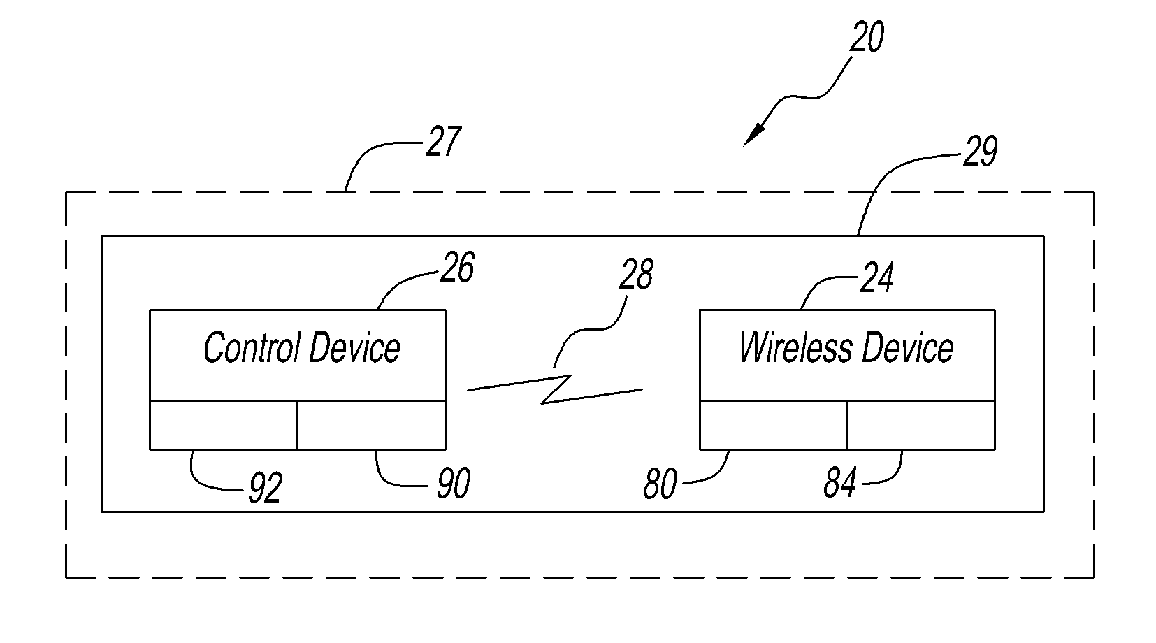
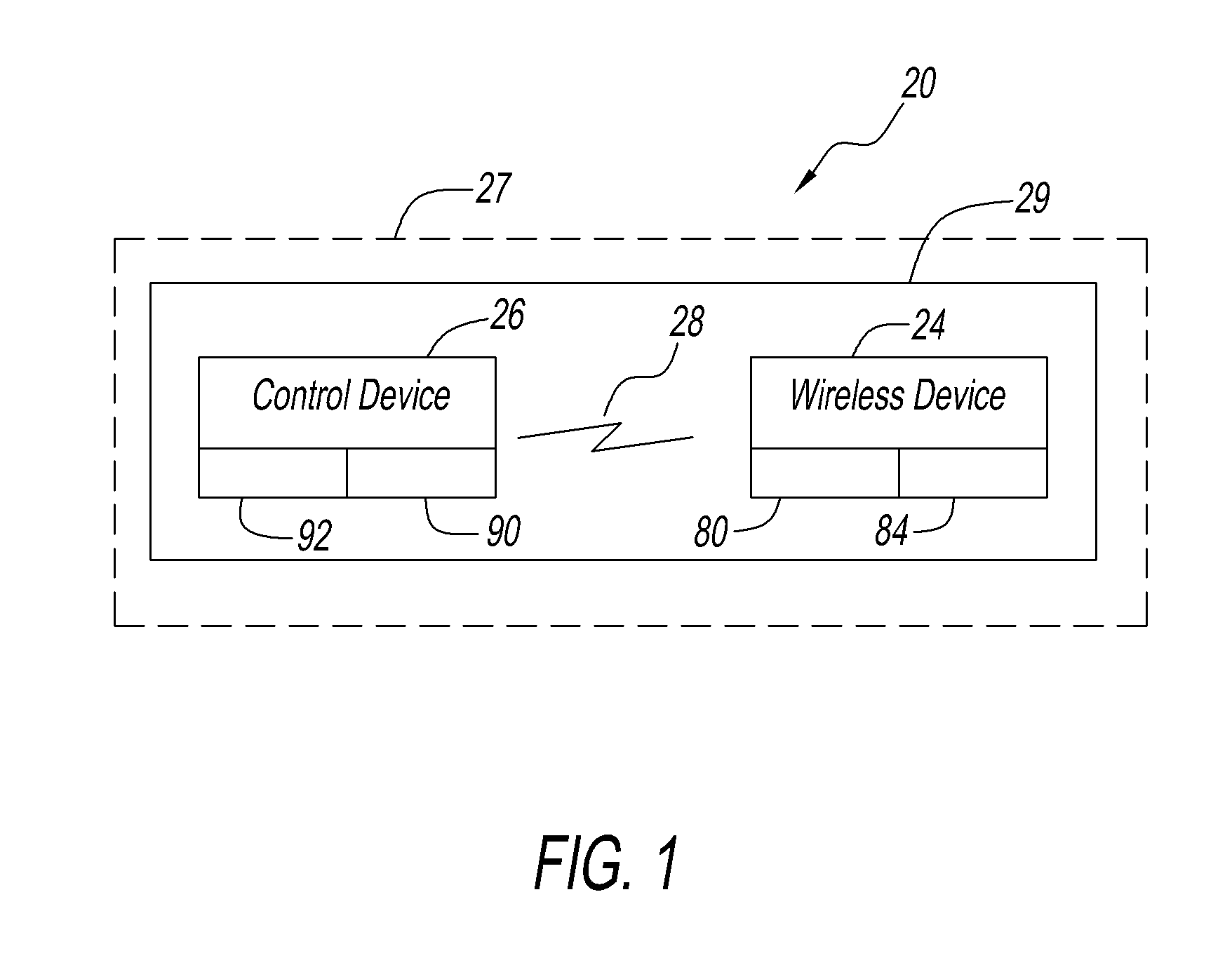
The present patent is related to a system that includes a control device and a wireless device that communicate with each other through a communication link with a reception range. The control device broadcasts a signal, and the wireless device receives the signal and sends a return signal back to the control device to determine if it is within the reception range. The control device then alerts the user if the wireless device is not within the reception range. The system can be used in various food service equipment such as oven, grill, etc. The wireless device can also have a sensor to sense various parameters such as temperature, humidity, pressure, etc. The technical effect of the patent is to provide an efficient and effective way to communicate between the control device and the wireless device for various applications in food service equipment.

Problems solved by technology

However, these systems lack an ability to determine that the object is lost or moved outside of a reception range of the reader.
If the tagged object is portable, a problem arises when the reader does not receive the return RF signal due to either failure or transport of the portable device out of a reception range of the reader.
If the portable device is missing, there is no immediate response and the activity of the apparatus may be shut down.

Method used


Image

  • Continuously monitored core temperature sensor and method
  • Continuously monitored core temperature sensor and method
  • Continuously monitored core temperature sensor and method

Examples


Embodiment Construction

[0023]The system of the present disclosure has utility in many applications in which a wireless device and a control device communicate with one another via a wireless communication link. For example, a parameter detected by the wireless device is communicated via the wireless communication link to the control device. The parameter may be selected selected from the group consisting of: temperature, humidity, pressure, barcode signal, video signal, aroma, gas-air composite, lambda value, oxygen sensor, pH value, alkaline value, conductance, color, density, weight, volume, length, mass, time, electric current, light intensity and force.

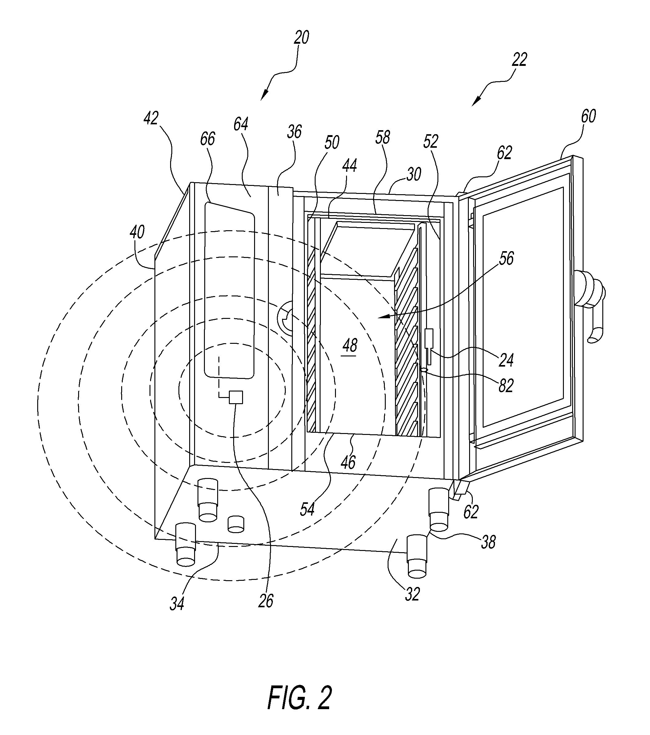
[0024]System 20, for example, can be used in the food service industry for a food service equipment that is a member of the group consisting of: oven, grill, broiler, food warmer, food display, ice making equipment, refrigeration equipment, beverage dispensing equipment, steamers, convection ovens, combination ovens, kettles, braising pans, skillets, fr...


PUM


Abstract

A system that provides notice of a lost signal. A wireless device and a control device employ radio frequency identification (RFID) technology, which uses radio frequency signals to communicate with one another via communication link having a reception range. The control device transmits a signal to the wireless device via the communication link. The wireless device responds by transmitting a return signal via the communication link. The control device processes the return signal to determine if the wireless device is within the reception range, if not, the control device provides an audible, written or visual alarm.

Description

RELATED APPLICATION[0001]This application claims the priority of U.S. Provisional Patent Application Ser. No. 61 / 581,871, filed on Dec. 30, 2011, the entire contents of which are incorporated herein.BACKGROUND[0002]1. Field of the Disclosure[0003]This disclosure relates to a system and a method that detects movement of a wireless device.[0004]2. Background of the Disclosure[0005]Radio-Frequency Identification (RFID) technology is typically used to transfer data from an electronic tag attached to an object for the purpose of tracking or identifying the object. The RFID tag includes an RF transmitter and an RF receiver. An RF reader device transmits an encoded RF signal to interrogate the tag. Upon receipt of the transmitted RF signal, the tag transmits a return RF signal with its identification information. RFID technology has been used in many applications to track inventory, assets, people and others. For example, the tag may be attached to cars, computer equipment, books, mobile p...

Claims


Application Information

Patent Timeline
IPC IPC(8): G06K7/00H04W4/80
CPCG06K7/0008F24C7/082G07C9/00G08B13/1427G08B21/0247G08B21/0275G01K1/024F25D2700/16H04W4/80
Inventor WILD, HANNES
Owner MIELE & CO KG
Learn More