Correction value derivation apparatus, displacement amount derivation apparatus, control apparatus, and correction value derivation method

Inactive Publication Date: 2014-01-30
CANON KK
View PDF3 Cites 7 Cited by
  • Summary
  • Abstract
  • Description
  • Claims
  • Application Information

AI Technical Summary

Benefits of technology

[0010]The present invention improves detection precision by r

Problems solved by technology

However, actual encoder output signals include harmonic components and nonlinear components, and are not ideal sine wave signals.
For this reason, even when errors of amplitudes, offsets, and phases of the encoder output signals are corrected, the corrected signals are no

Method used


Image

  • Correction value derivation apparatus, displacement amount derivation apparatus, control apparatus, and correction value derivation method
  • Correction value derivation apparatus, displacement amount derivation apparatus, control apparatus, and correction value derivation method
  • Correction value derivation apparatus, displacement amount derivation apparatus, control apparatus, and correction value derivation method

Examples


first embodiment

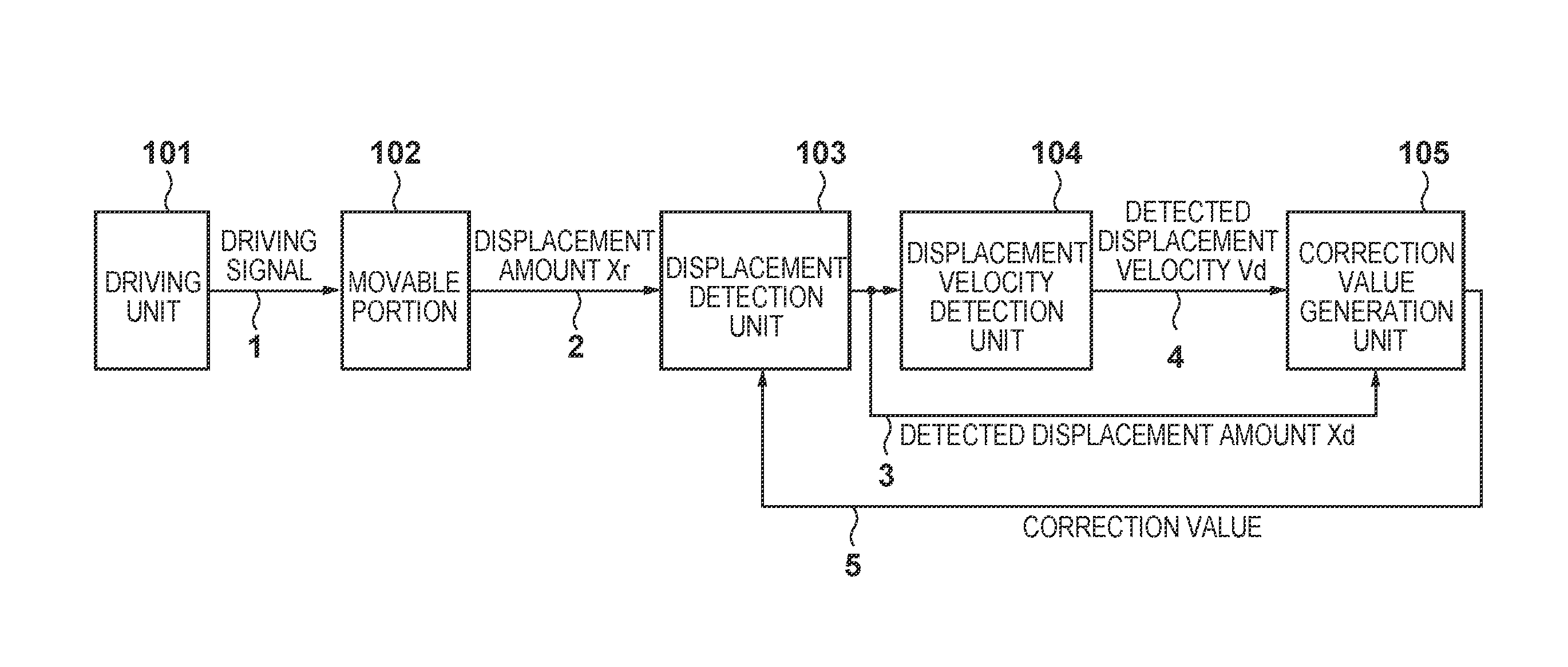
[0041]A displacement detection unit 103 mounted in a motor control apparatus will be exemplified below as the first embodiment of a signal processing apparatus according to the present invention.

[0042]Arrangement of Motor Control Apparatus>

[0043]FIG. 7 is a schematic view of a motor control apparatus. Reference numeral 700a denotes an overall view of a motor control apparatus; and 700b, a schematic plan view of an encoder scale 702. The motor control apparatus 700a includes an optical encoder required to detect a rotation angle (displacement amount) of a motor shaft of a rotary motor 705.

[0044]The encoder includes an encoder scale 702 having a rotary slit disc and fixed slit disc, and a sensor unit 703 having a light-emitting element (light-emitting diode) and light-receiving element (photodiode). The rotary slit disc is attached to the motor shaft of the rotary motor 705, and is rotated together with the motor shaft. On the other hand, the fixed slit disc and the sensor unit 703 ar...

second embodiment

[0094]The second embodiment will explain another arrangement of a displacement detection unit 103. More specifically, correction processing is executed in interpolation processing unlike in the first embodiment. Differences from the first embodiment will be mainly described below.

[0095]

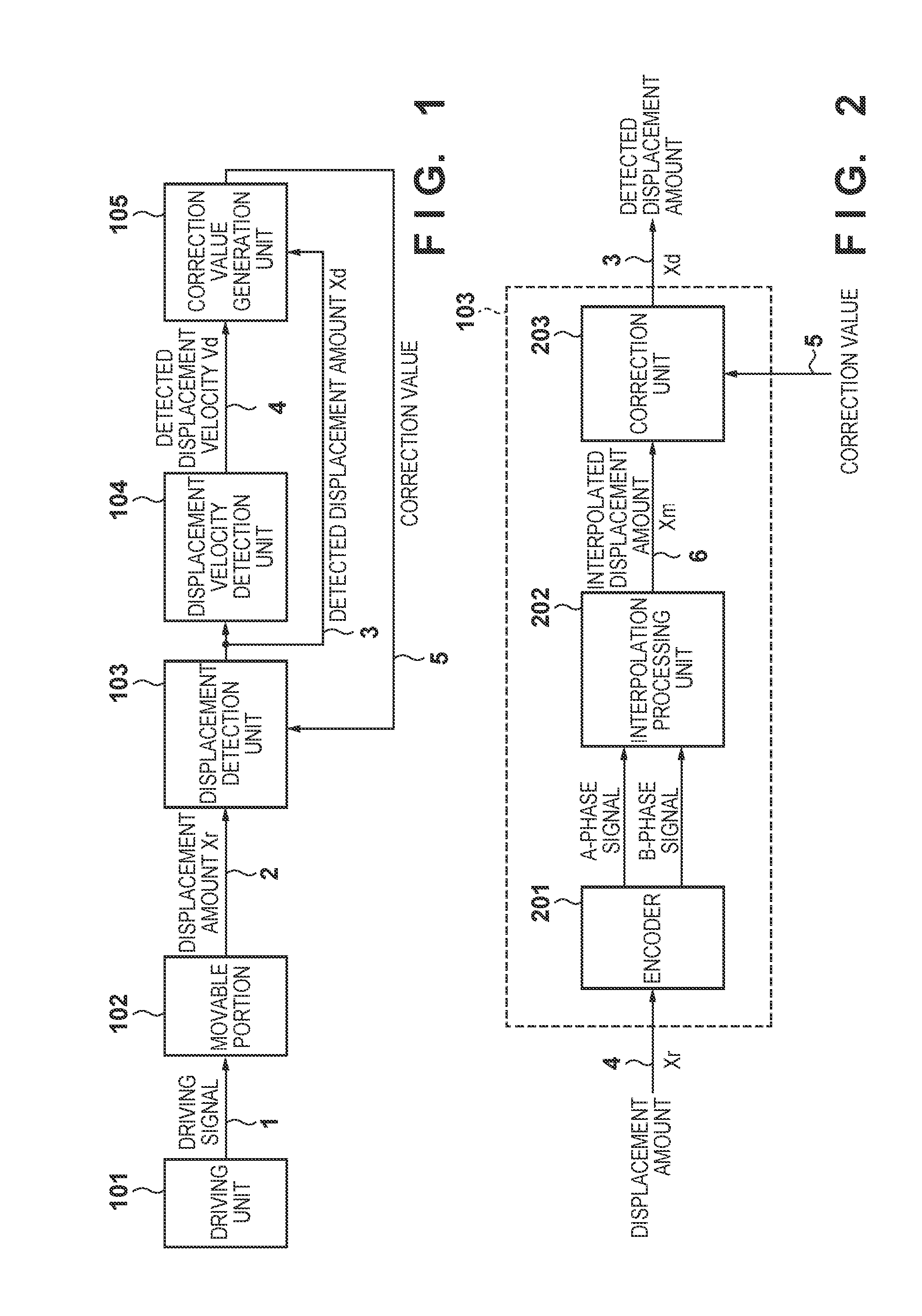
[0096]FIG. 8 is a block diagram showing an example of the arrangement of a displacement detection unit according to the second embodiment. A displacement detection unit 103 detects a true displacement amount Xr of a movable portion, and outputs a detected displacement amount Xd. An encoder 201, which is synchronized with a movable portion 102, generates encoder signals shown in FIG. 27 in accordance with the true displacement amount Xr, and outputs these signals to an interpolation processing unit 801 with correction.

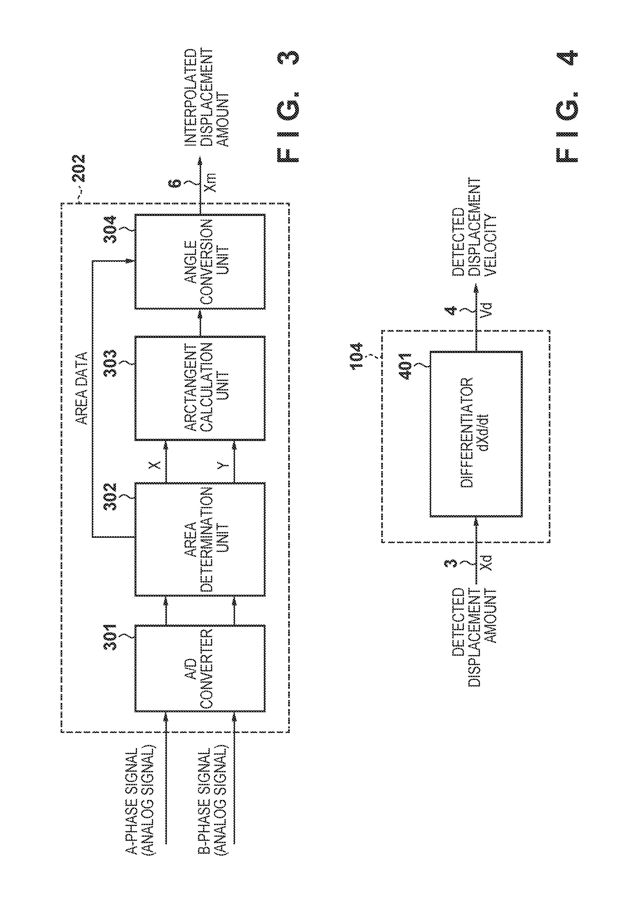
[0097]FIG. 9 is a block diagram showing an example of the arrangement of the interpolation processing unit with correction. An analog / digital (A / D) converter 301 is used to convert two-ph...


PUM


Abstract

This invention improves detection precision by reducing a detection error of a change in position of a target. A correction value derivation apparatus for deriving a correction value used in correction of a displacement amount derived based on an encoder signal indicating a change in position of a movable portion as a target, comprises: a displacement amount derivation unit configured to derive a detected displacement amount of the movable portion based on the encoder signal; a displacement velocity derivation unit configured to derive a detected displacement velocity based on the detected displacement amount derived by the displacement amount derivation unit; an average displacement velocity calculation unit configured to calculate an average displacement velocity over a predetermined displacement range; and a correction value derivation unit configured to derive the correction value based on the detected displacement velocity and the average displacement velocity.

Description

BACKGROUND OF THE INVENTION[0001]1. Field of the Invention[0002]The present invention relates to a technique for processing an encoder signal indicating a phase change of a position or angle of a target.[0003]2. Description of the Related Art[0004]In general, an optical rotary encoder is popularly used to detect a moving amount, angle, position, and the like of a rotation member of a motor or the like. A rotary encoder of this type irradiates a rotation signal screen provided with a required signal pattern with uniform light from a light-emitting element including a light-emitting diode (LED) or the like from one side. Then, a light-receiving element such as a photodiode or phototransistor receives and detects transmission light which has transmitted through the signal pattern or reflected light from the signal screen, thus forming an electric signal pattern. An encoder output signal is generated based on the electric signal pattern. As functional segmentations of the encoder, an in...

Claims


Application Information

Patent Timeline
IPC IPC(8): G01D5/244
CPCG01D5/24476G01D5/24495G01D5/247G01D5/244
Inventor MIZOGUCHI, MASAHIKO
Owner CANON KK
Why Eureka
Try Eureka