
Wind turbine blade having a root region with elongated fastening members provided with metal fibres

a technology of metal fibres and fastening members, which is applied in the direction of propellers, propulsive elements, water-acting propulsive elements, etc., can solve the problems of insufficient documentation, failure of the connection between the blade root and the hub, and the failure of the fastening member to be retained, so as to improve the retention of the fastening member. , the effect of improving the diameter of the root region

Active Publication Date: 2014-01-30
LM WP PATENT HLDG
View PDF5 Cites 24 Cited by
  • Summary
  • Abstract
  • Description
  • Claims
  • Application Information

AI Technical Summary

Benefits of technology

This patent describes a way to attach blades to a wind turbine hub using a composite material. The metal fibers embedded in the material provide better retention and allow for longer and heavier blades to be attached without increasing the size of the hub. The corrugated surface of the attachment element also improves adhesion to the composite material. Overall, this method ensures a reliable and durable attachment of blades to the wind turbine.

Problems solved by technology

A potential problem in connection with wind turbine blades is load transfer from the fibre composite structure of the root region to the hub of the wind turbine.
This may result in the root connection being insufficiently supported to withstand the loads, whereby the connection between the blade root and the hub may fail since the bushings are insufficiently retained in the composite material and thus pulled out of the composite material of the root region.
This is especially a problem when long and thereby heavy blades are to be used.
However, the document does not address the problem of how the root region is to be designed to withstand extreme loads in the connection between the blade root and the hub.

Method used


Image

  • Wind turbine blade having a root region with elongated fastening members provided with metal fibres
  • Wind turbine blade having a root region with elongated fastening members provided with metal fibres
  • Wind turbine blade having a root region with elongated fastening members provided with metal fibres

Examples


second embodiment

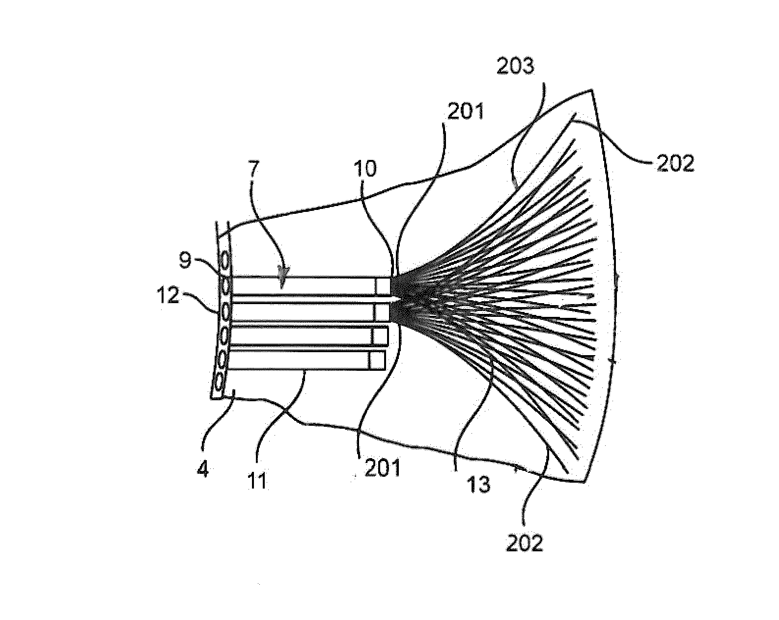
[0107]FIG. 5 shows the bushing 7 comprising metal fibres 13 firmly fixed to the outer periphery 11 of the bushing 7. The outer periphery of the bushing 7 is corrugated so as to increase the surface area thereof.

third embodiment

[0108]FIG. 6A shows a bushing 7 provided with outwardly extending metal fibres 13. The metal fibres 13 are arranged in unidirectional fibre bundles 204. Each bundle 204 is firmly fixed to the second end 10 of the bushing 7. The bundle 204 is fixed to the second end 10 in separate circular rows. A first circular row is placed near the periphery of the second end 10 and a second circular row is placed inwardly of the first row. The bushing 7 and the fibre bundles 204 are embedded in the polymer matrix of the fibre-reinforced composite material of the root region. Additional fibres, such as steel fibres or fibres of a different material than metal, are preferably placed in the area between the bundles 204. The fibre bundles 204 are firmly fixed to the bushings 7 as explained above.

fourth embodiment

[0109]FIG. 6B shows a bushing 7 comprising metal fibres 13. The metal fibres 13 are arranged unidirectionally and each of the fibres is separately firmly fixed to the bushing 7.


PUM

PropertyMeasurementUnit
Fractionaaaaaaaaaa
Fractionaaaaaaaaaa
Fractionaaaaaaaaaa

Abstract

A wind turbine blade for a wind turbine is a shell structure of a fibre-reinforced composite and comprises a root region and an airfoil region. The root region has ring-shaped cross section and comprises a plurality of elongated bushings 7 with an inner thread 22 and embedded interspaced in the fibre-reinforced polymer so as to substantially follow the circumference of the root region and allow access from the outside to the inner threads. Each fastening member 7 is provided with a notch 60′ in the periphery 11 thereof. A rod-shaped locking element 61 passes through the notch 60′ in engagement therewith. The locking element 61 is fixedly and tightly fitting arranged in a through-going circular bore 65 extending through the wall of the root region.

Description

TECHNICAL FIELD[0001]The present invention relates to a wind turbine blade for a wind turbine rotor comprising a hub from which the wind turbine blade extends when mounted to the hub, the wind turbine blade including a shell structure of a fibre-reinforced composite material comprising fibres embedded in a polymer matrix, the wind turbine blade extending in longitudinal direction and having a profiled contour including a pressure side and a suction side as well as a leading edge and a trailing edge, said edges defining a chord plane therebetween, when seen in the longitudinal direction the profiled contour comprising a root region with a root end face, an airfoil region and optionally a transition region between the root region and the airfoil region, the root region having a ring-shaped cross section with an outer surface and an inner surface, the root region comprising a plurality of elongated fastening members provided with fastening means and embedded mutually spaced apart in th...

Claims


Application Information

Patent Timeline
IPC IPC(8): F03D1/06
CPCF03D1/0658B29C70/885F03D1/0675F05B2230/21F05B2230/237F05B2230/238F05B2280/10F05B2280/1071F05B2280/4003F05B2280/6003F05B2280/6013F05B2280/702Y02E10/72Y02P70/50
Inventor DAHL, MARTINMORTENSEN, BJARNE KRABHORNBLOW, BENJAMIN
Owner LM WP PATENT HLDG
Learn More