Wrapping machine and method

a technology of wrapping machine and load, which is applied in the direction of wrapping/bundling articles, packaging goods, special packaging, etc., can solve the problems of compromising stability, affecting the product quality of the product, and the rotation speed of the carousel must be limited, so as to achieve rapid and efficient wrapping, reduce the effect of affecting the product quality and the effect of product quality improvemen

Active Publication Date: 2014-02-06
AETNA GROUP
View PDF11 Cites 49 Cited by
  • Summary
  • Abstract
  • Description
  • Claims
  • Application Information

AI Technical Summary

Benefits of technology

[0019]Another object is to make a wrapping machine and wrapping method that enable productivity to be considerably increased compared with known machines and wrapping methods.
[0020]A further object is to obtain a wrapping machine and a wrapping method that enable loads to be wrapped rapidly and efficiently that consist of a plurality of partial loads to be bound first separately and then jointly

Problems solved by technology

In the latter, in fact, the rotation speed of the carousel has to be limited because of the centrifugal forces that are generated on the load and can compromise the stability thereof (typically in the case of a plurality of products grouped on a pallet).
One limit of known wrapping machines, also of the most efficient and fastest machines, resides in the fact that the load has to be introduced into the machine before wrapping and then extracted from the machine once it is completed.
Such operating steps of introduction and extraction of the load require time and reduce considerably machine productivity.
In fact, a subsequent load cannot be wrapped until a work area of the wrapping machine (for example a zone underneath the rotating ring or the rotating carousel) has not been freed of the previous load.
This drawback is clear, for example when the final load to be wrapped consists of a plurality of partial loads or groups of products to be wrapped first separately and then jointly.
In this case, the time required for moving the single partial loads and the final load inside and outside significantly affects overall binding time, reducing machine productivity.
Further, due to the number and the arrangement of the conveying apparatuses, the wrapping system is very bulk

Method used


Image

  • Wrapping machine and method
  • Wrapping machine and method
  • Wrapping machine and method

Examples


Embodiment Construction

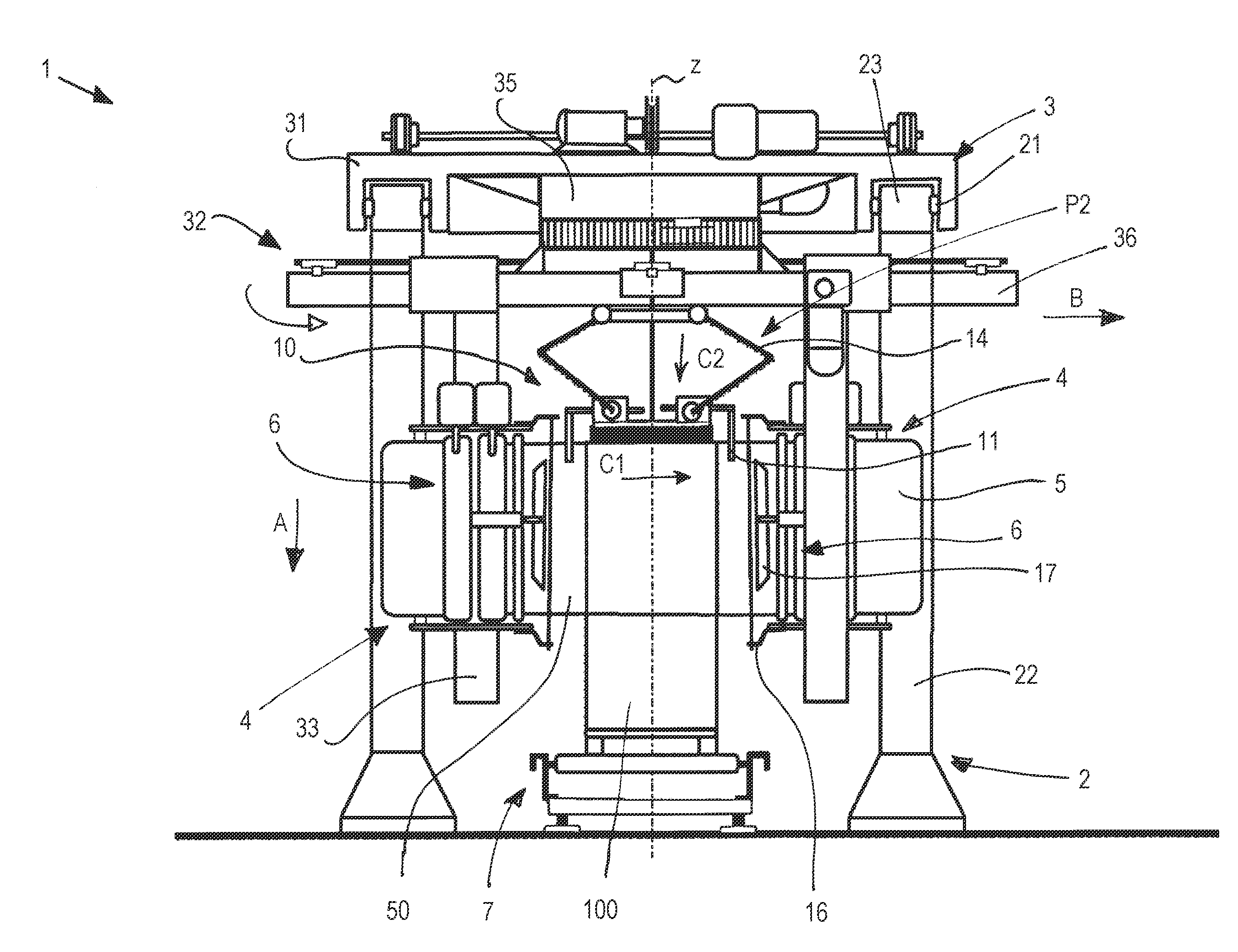
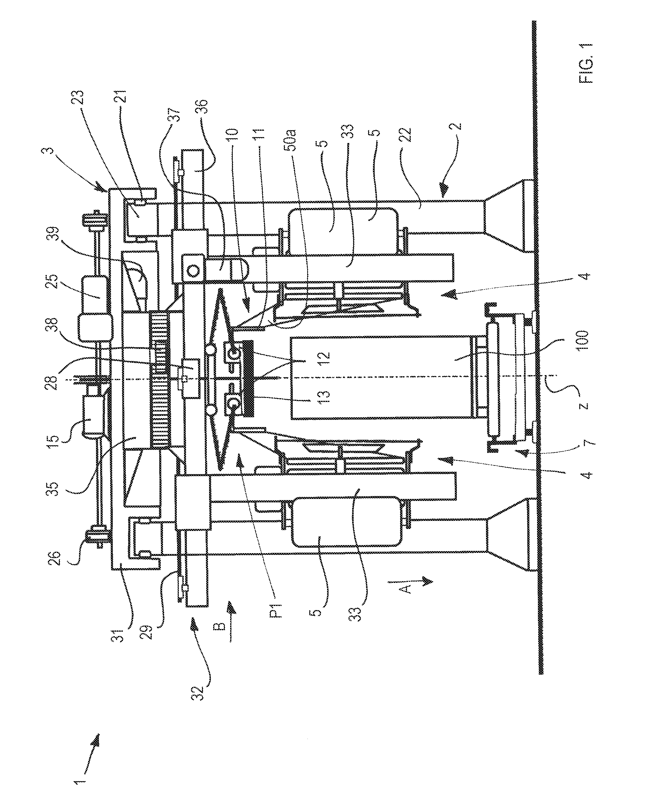
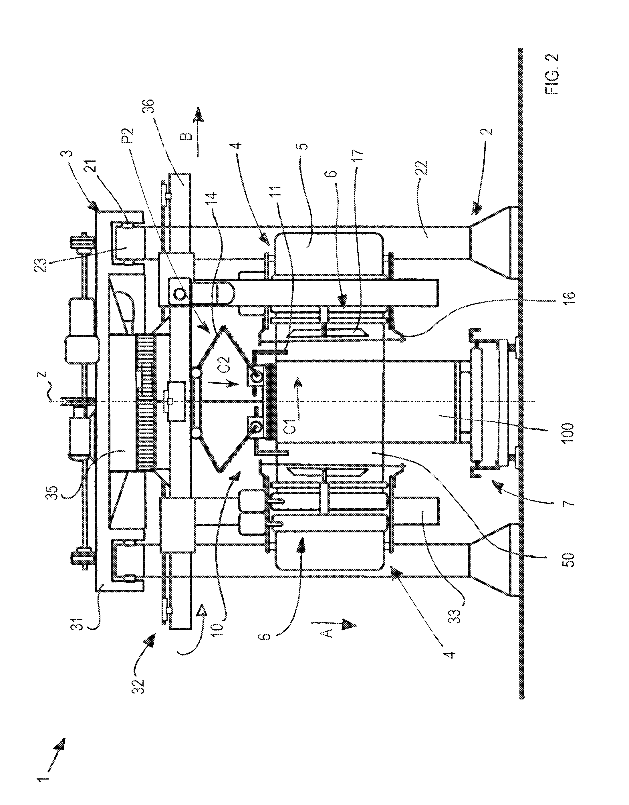
[0032]With reference to FIGS. 1 to 4, a machine is illustrated for wrapping a load 100 with a film 50 made of plastic material comprising a first frame 2 and a second frame 3. The latter are supported by the first frame 2 and in turn support rotatably around and slidably parallel along a wrapping axis Z one or more wrapping units 4, each of which comprise a reel 5 of film 50 and a roller assembly 6 arranged for unwinding and possibly prestretching the film 50. The roller assembly 6 includes in particular a pair of prestretching rollers 61, 62 for example driven by respective motors 63, 64, to unwind the film from the reel 5 and prestretch the film by a defined percentage, and one or more transmission rollers 66.

[0033]The second frame 3 is slidably mounted on the first frame 2 such as to be movable along an advancing direction X that is transverse to the wrapping axis Z, in particular orthogonal to the latter. The first frame 2 defines a work area W inside which the wrapping units 4 ...


PUM

PropertyMeasurementUnit
Speedaaaaaaaaaa
Distanceaaaaaaaaaa

Abstract

A machine for wrapping a load with a film made of synthetic plastics includes a first frame suitable for supporting second frame that rotatably supports around, and slidably parallel to, a wrapping axis at least one wrapping unit including a reel of the film and a roller assembly arranged for unwinding and prestretching the film. The second frame is slidably mounted on the first frame and is movable along an advancing direction that is transverse, and in particular orthogonal, to the wrapping axis. A conveyor is provided for moving the load along the advancing direction. The conveyor and the second frame are movable in a mutually coordinated manner to wrap the load with the film also while the load is moved along the advancing direction.

Description

[0001]This application is a §371 National Stage Entry of PCT International Application No. PCT / IB2012 / 051745 filed Apr. 10, 2012. PCT / IB2012 / 051745 claims priority to IT Application No. MO2011A000074 filed Apr. 11, 2011 and IT Application No. MO2011A000075 filed Apr. 11, 2011 and IT Application No. MO2011A000076 filed Apr. 11, 2011. The entire contents of these applications are incorporated herein by reference.BACKGROUND OF THE INVENTION[0002]The invention relates to machines and methods for wrapping a load with a film made of extendible plastic material. In particular, the invention refers to a wrapping machine arranged for wrapping a film around a load to be packaged and to a corresponding wrapping method.BRIEF DISCUSSION OF THE PRIOR ART[0003]Known wrapping machines typically comprise a wrapping unit that supports a reel of film to be wrapped around the load (consisting of a product or a plurality of products grouped on a pallet), such as to form a series of pleated strips or ban...

Claims


Application Information

Patent Timeline
IPC IPC(8): B65B11/00
CPCB65B11/008B65B11/00B65B11/585B65B35/24B65B2011/002B65B2210/20
Inventor CERE', MAURO
Owner AETNA GROUP
Why Eureka
Try Eureka