
Plate-fin structure exhaust gas recirculation cooler with heat-insulation function

a technology of platefin structure and cooler, which is applied in the direction of machines/engines, safety devices for heat exchange apparatus, light and heating equipment, etc., can solve the problems of axial stress, cracking of the welded joint at the end of the main board and the flat pipe unit, etc., and achieve the effect of increasing the strength of the shell

Active Publication Date: 2014-02-06
ZHEJIANG YINLUN MACHINERY
View PDF4 Cites 25 Cited by
  • Summary
  • Abstract
  • Description
  • Claims
  • Application Information

AI Technical Summary

Benefits of technology

The present invention aims to improve the heat dissipation effect and reliability of an EGR cooler. The technical effect of the invention is to address the problems in the prior art by providing a better solution for cooling the EGR.

Problems solved by technology

The regular plate-fin structure EGR cooler has the following disadvantages: 1. when the EGR cooler is in operation, the high-temperature exhaust gas impact the main board of the EGR cooler and the main board will expand to generate stress; 2. during the operation of the EGR, the different expansion and contraction of the shell and the flat pipe unit result in axial stress.
The stress generated due the above two points can easily lead to the cracking of the welded joint at the ends of the main board and the flat pipe unit.

Method used


Image

  • Plate-fin structure exhaust gas recirculation cooler with heat-insulation function
  • Plate-fin structure exhaust gas recirculation cooler with heat-insulation function
  • Plate-fin structure exhaust gas recirculation cooler with heat-insulation function

Examples


Embodiment Construction

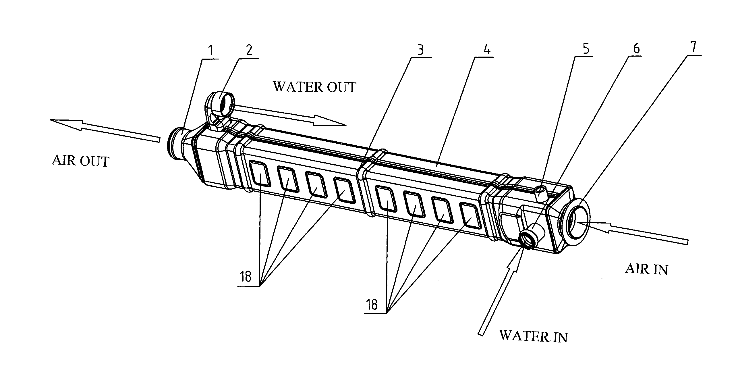
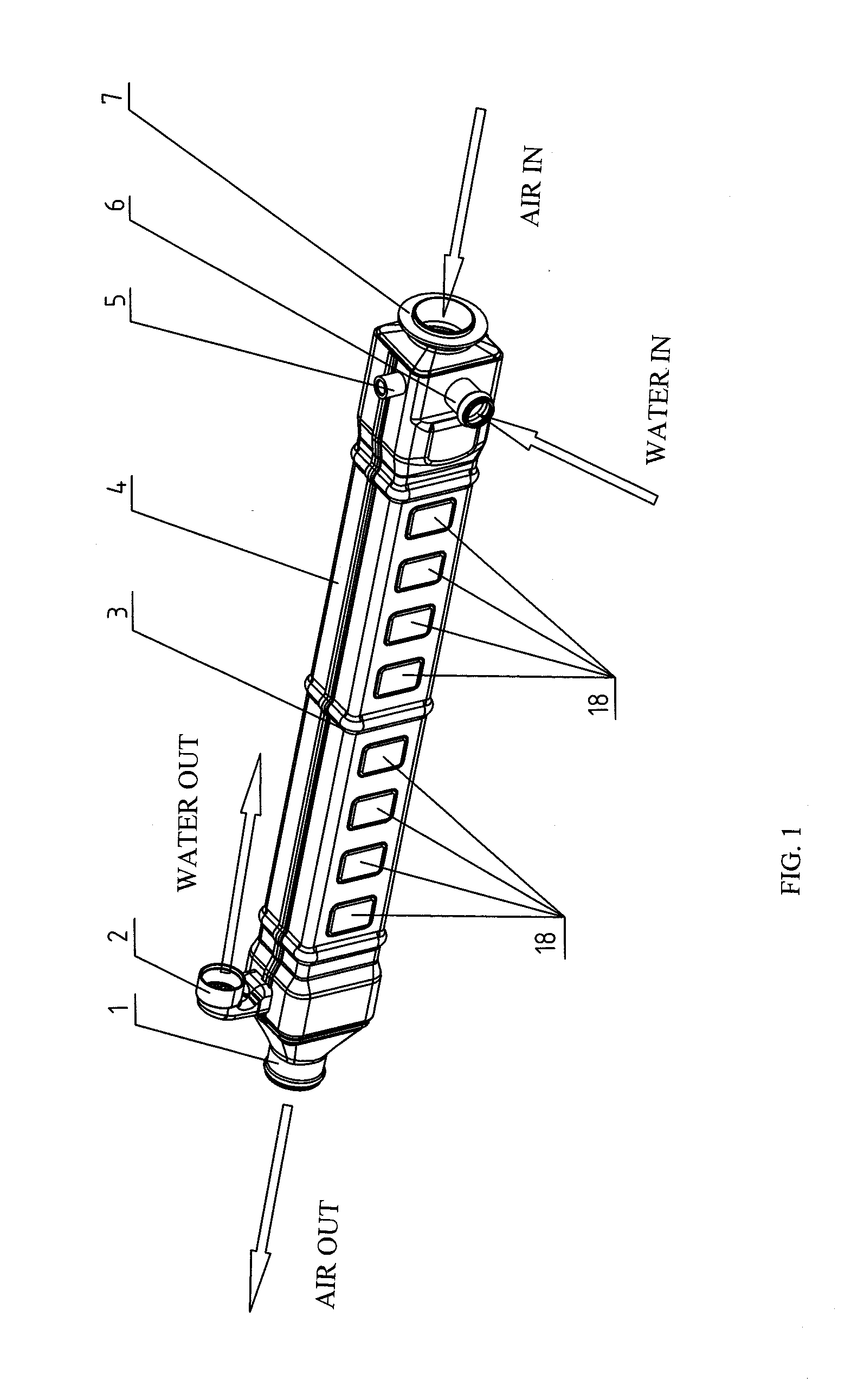
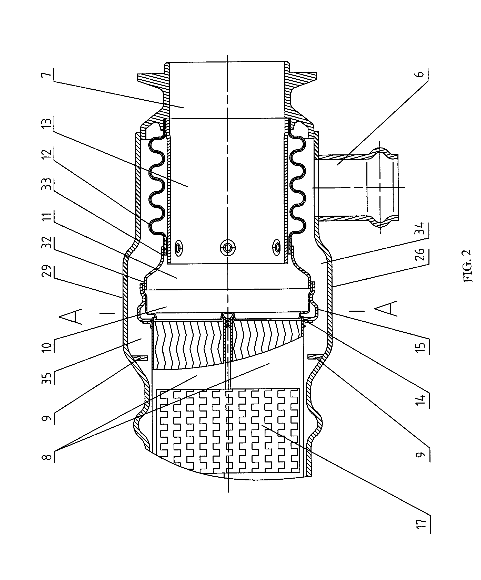
[0033]As FIGS. 1-9 show, the plate-fin structure EGR cooler with heat-insulating function of the present invention comprises a front shell 3 and a back shell 4, two ends of which are equipped with an air inlet flange 7 and a discharging chamber 1. A water inlet and an outlet are equipped on the shell near the air inlet flange 7 and the discharging chamber 1. The water inlet and the water outlet are connected to a water inlet pipe 6 and an outlet pipe 2, respectively. A cooling core assembly, an air chamber 11 and a bellow 12 are installed within the shells 3,4.

[0034]The cooling core assembly comprises main boards 15 and 27 at its two ends, sub-main boards 14 and 28 at the internal sides of the main board, and upper and lower groups of flat pipe units 8. Each flat pipes unit 8 includes a flat pipe and a heat transfer fin installed therein. The flat pipe units 8 of upper and lower group are set in pair and a water-side fin 17 is set between each two pair of units 8. As FIG. 6 shows, s...


PUM


Abstract

The present invention discloses a plate-fin structure EGR cooler with heat-insulation function includes shell. The two ends of the shell are equipped with an air inlet flange and a discharge chamber. A water inlet pipe and a water outlet pipe are set on the shell near the air inlet flange and the discharge chamber. A cooling core assembly, an air chamber and a bellow are set in the shell. The main board at one end of the cooling core assembly is connected to the shell and the discharge chamber and the main board at another end is connected to one end of the air chamber. The other end of the air chamber is connected to one end of the bellow. The other end of the bellow is connected to the shell and the air inlet flange. A heat-insulating pipe connected to the air inlet flange is set within the bellow. Since the main board at the other side of the cooling core assembly is flexibly connected to the shell via the air chamber and the bellow, the axial deformation generated in the flat pipe unit can be transferred to and absorbed by the bellow through the air chamber and thus the axial heat stress generated from the heat deformation of the flat pipe unit is eliminated.

Description

FIELD OF THE INVENTION[0001]The present invention relates to engine exhaust gas cooling technology, especially a plate-fin structure exhaust gas recirculation (EGR) cooler for diesel engines. More specifically, it is a plate-fin structure EGR cooler with heat-insulation function that can be widely used in diesel engines of various types of automobiles.BACKGROUND OF THE INVENTION[0002]With the increasingly strict regulations on emission, exhaust gas recirculation technology has been applied in power unit more widely and the EGR coolers of various structures have been invented in succession. Among them, the plate-fin EGR cooler has gained more popularity due to its excellent heat dissipation performance.[0003]The increasingly strict regulations on emission drive the improvement of the EGR rate, namely, the exhaust gas flow needed to be cooled by the EGR cooler is on the increase. Besides, many EGRs are set before the turbo, making them high-pressure EGRs which results in the exhaust g...

Claims


Application Information

Patent Timeline
IPC IPC(8): F02M25/07
CPCF02M25/07F28D7/1684F28D21/0003F28F1/08F28F9/02F28F9/0239F28F9/0241F28F9/0248F28F9/20F28F2265/26F02M26/32Y02T10/12
Inventor ZHANG, WENFENGGUAN, BAIJUNLIU, HAOHU, YIHONGQIN, XIAOJUNZHAO, YOUQIYANG, LIANMINZHANG, SHOUDUXU, KAIJUNLU, QINGSONGCHEN, LUYING
Owner ZHEJIANG YINLUN MACHINERY
Learn More