Residue hydrocracking

Inactive Publication Date: 2014-02-06
LUMMUS TECH INC
View PDF5 Cites 22 Cited by
  • Summary
  • Abstract
  • Description
  • Claims
  • Application Information

AI Technical Summary

Benefits of technology

The patent describes a process for upgrading residuum hydrocarbons and reducing the tendency of the resulting products to form asphaltenic sediment in downstream processes. The process involves contacting the residuum hydrocarbon fraction and hydrogen with a hydroconversion catalyst in a hydrocracking reaction zone to convert at least a portion of the residuum hydrocarbon fraction to lighter hydrocarbons. The resulting effluent is then contacted with hydrogen and a resid hydrotreating catalyst, and separated to recover two or more hydrocarbon fractions. The technical effect of this process is the reduction of the tendency of the resulting products to form asphaltenic sediment in downstream processes, which can improve the overall quality of the upgraded residuum hydrocarbons.

Problems solved by technology

However, sediment deposition remains a challenge.
Precipitation of asphaltenic material (“sediment”) is a major issue in most, if not all, high conversion residue hydrocracking units, especially those utilizing ebullated bed hydrocracking, and often limits the extent of conversion and reduces the on stream factor of many units.
Additionally, products from ebullated bed hydrocracking are typically of lower quality, as a significant portion of the conversion occurs as a result of thermal cracking and a contribution of catalytic hydroconversion that improves product quality is somewhat limited.

Method used


Image

  • Residue hydrocracking
  • Residue hydrocracking
  • Residue hydrocracking

Examples


example 1

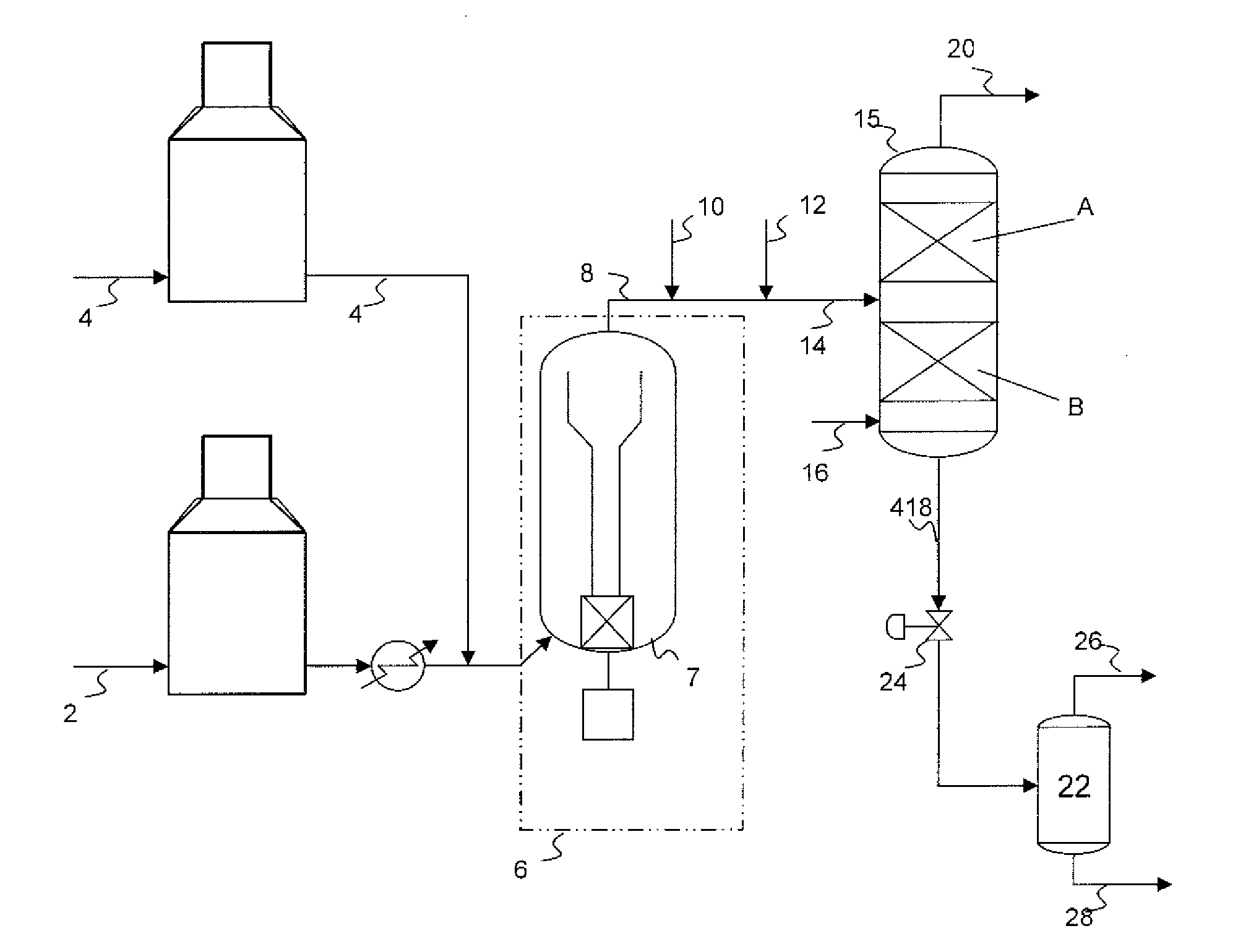
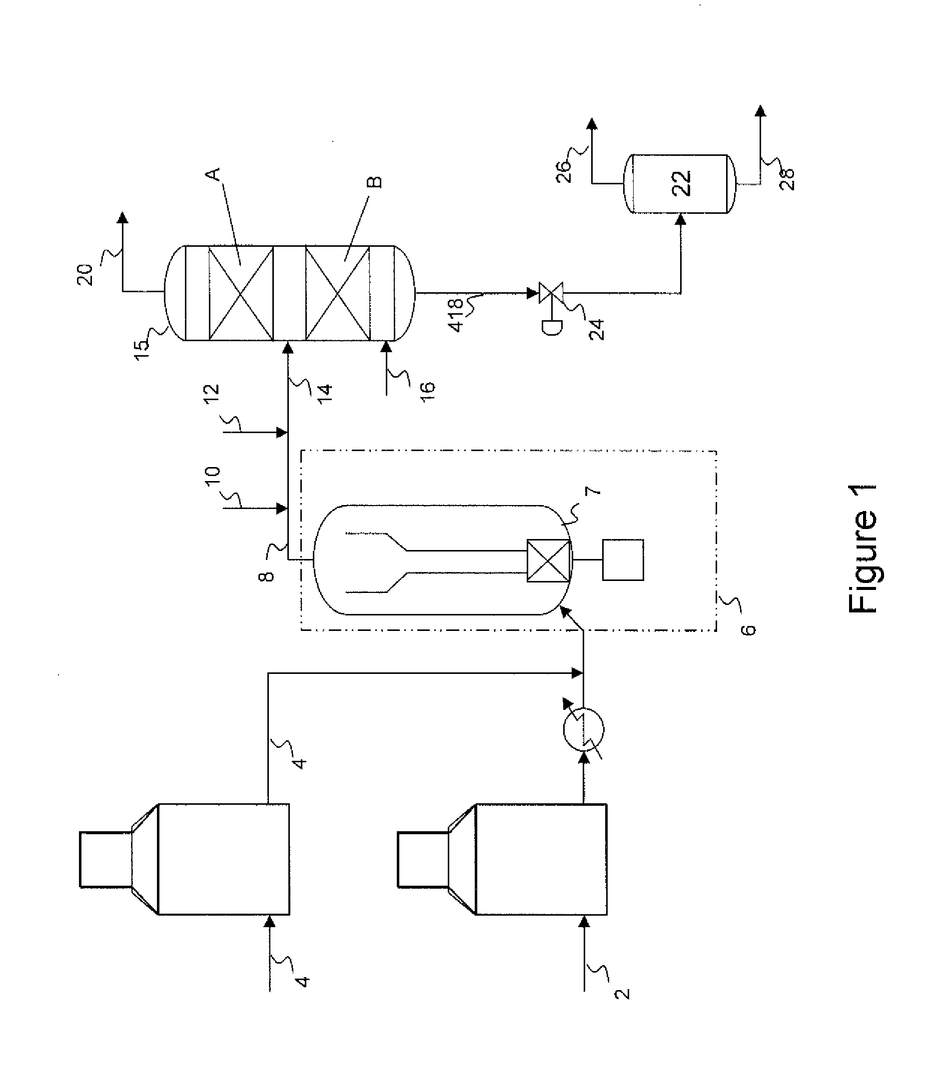
[0050]A first theoretical example is described with reference to FIG. 1 illustrating the effect the addition of a reactor / stripper has on the heavy unconverted oil and distillate product qualities. Specifically in this example the ebullated bed hydrocracking stage operates at a liquid hourly space velocity of 0.25 hr-1 and a temperature between 425° C. and 432° C., converting between 65 to 73% of the vacuum residue fraction in the feed. In addition approximately 75% of sulfur, 80% of the metals, 60% of the CCR and 65% of the asphaltenes in the residue feed is removed in this hydrocracking stage.

[0051]The resulting heavy unconverted oil product after quenching then flows downward through the residue hydrotreating catalyst bed where it contacts hydrogen flowing upward and countercurrent to the unconverted oil which undergoes further reaction. In this bed the unconverted residue fraction undergoes further desulfurization, demetallation and Conradson Carbon Reduction and asphaltene conv...

example 2

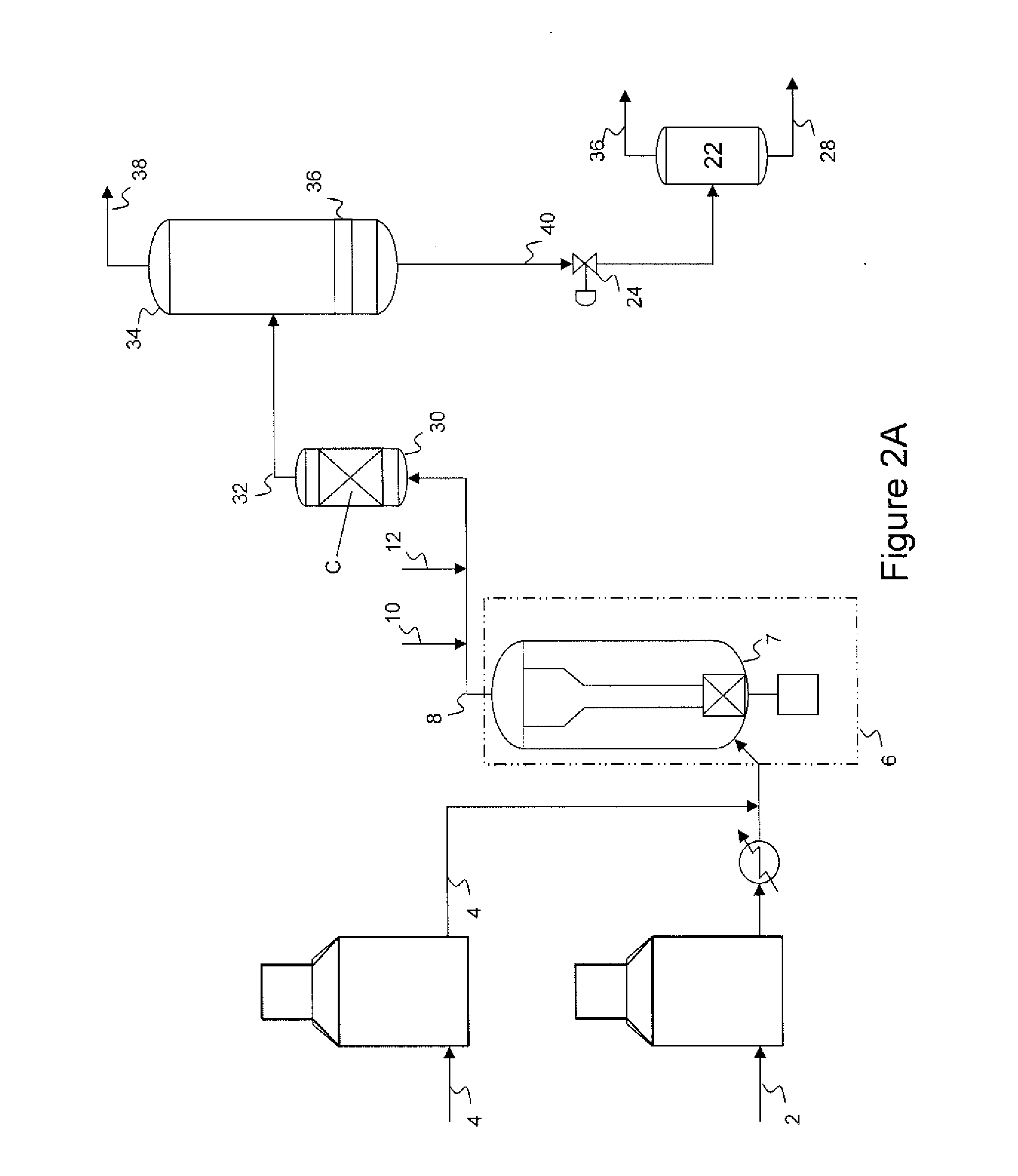
[0054]A second theoretical example is described with reference to FIG. 2B illustrating the combined effect the addition of an upflow or OCR reactor and subsequent reactor / stripper has on residue conversion, reaction yields and heavy unconverted oil and distillate product qualities. As in Example 1, it is envisaged that the ebullated bed hydrocracking stage operates at a LHSV of 0.25 hr-1 and a temperature of 425° C. to 432° C., converting between 65 and 73 of the vacuum residue fraction in the feed. In addition, as in Example 1 approximately 75% of the sulfur, 80% of the metals, 60% of the CCR and 65% of the asphaltenes in the residue feed is removed in the hydrocracking stage.

[0055]In Example 2, the liquid and vapor effluent from the hydrocracking reaction stage after being quenched is further processed in an upflow reactor, containing residue hydroprocessing catalyst, thereby providing for additional sulfur, metals, CCR and asphaltene removal. It is envisaged that the upflow react...


PUM


Abstract

A process for upgrading residuum hydrocarbons and decreasing tendency of the resulting products toward asphaltenic sediment formation in downstream processes is disclosed. The process may include: contacting a residuum hydrocarbon fraction and hydrogen with a hydroconversion catalyst in a hydrocracking reaction zone to convert at least a portion of the residuum hydrocarbon fraction to lighter hydrocarbons; recovering an effluent from the hydrocracking reaction zone; contacting hydrogen and at least a portion of the effluent with a resid hydrotreating catalyst; and separating the effluent to recover two or more hydrocarbon fractions.

Description

FIELD OF THE DISCLOSURE[0001]Embodiments disclosed herein relate generally to processes for hydrocracking residue and other heavy hydrocarbon fractions. More specifically, embodiments disclosed herein relate to processes for cracking residue and other heavy hydrocarbon fractions while simultaneously reducing asphaltenic sediment formation downstream of ebullated bed reactor systems and improving the quality of the conversion products.BACKGROUND[0002]Attempts to mitigate sediment deposition problems in equipment downstream of ebullated bed reactors, such as separators, exchangers, heaters, and fractionation equipment have used various chemical and mechanical means. However, sediment deposition remains a challenge. Precipitation of asphaltenic material (“sediment”) is a major issue in most, if not all, high conversion residue hydrocracking units, especially those utilizing ebullated bed hydrocracking, and often limits the extent of conversion and reduces the on stream factor of many u...

Claims


Application Information

Patent Timeline
IPC IPC(8): C10G65/12B01J8/00
CPCC10G65/00C10G65/12C10G65/14C10G45/02C10G2300/205C10G2300/202C10G2300/1077C10G2300/1074C10G2300/107C10G2300/1059
Inventor MUKHERJEE, UJJAL K.BALDASSARI, MARIO C.
Owner LUMMUS TECH INC
Why Eureka
Try Eureka