Selective Repositioning and Rotation Wavelength Beam Combining System and Method

Inactive Publication Date: 2014-02-06
TERADIODE
View PDF0 Cites 18 Cited by
  • Summary
  • Abstract
  • Description
  • Claims
  • Application Information

AI Technical Summary

Problems solved by technology

Furthermore, when broad-area optical gain elements are used the spectral utilization is poor.
Furthermore, since beam combining is performed along the stacking dimension or near diffraction-limited dimensi

Method used


Image

  • Selective Repositioning and Rotation Wavelength Beam Combining System and Method
  • Selective Repositioning and Rotation Wavelength Beam Combining System and Method
  • Selective Repositioning and Rotation Wavelength Beam Combining System and Method

Examples


Embodiment Construction

[0026]Aspects and embodiments relate generally to the field of scaling laser sources to high-power and high-brightness using wavelength beam combining techniques. More particularly, methods for increasing brightness, stability, and effectiveness of wavelength beam combining systems.

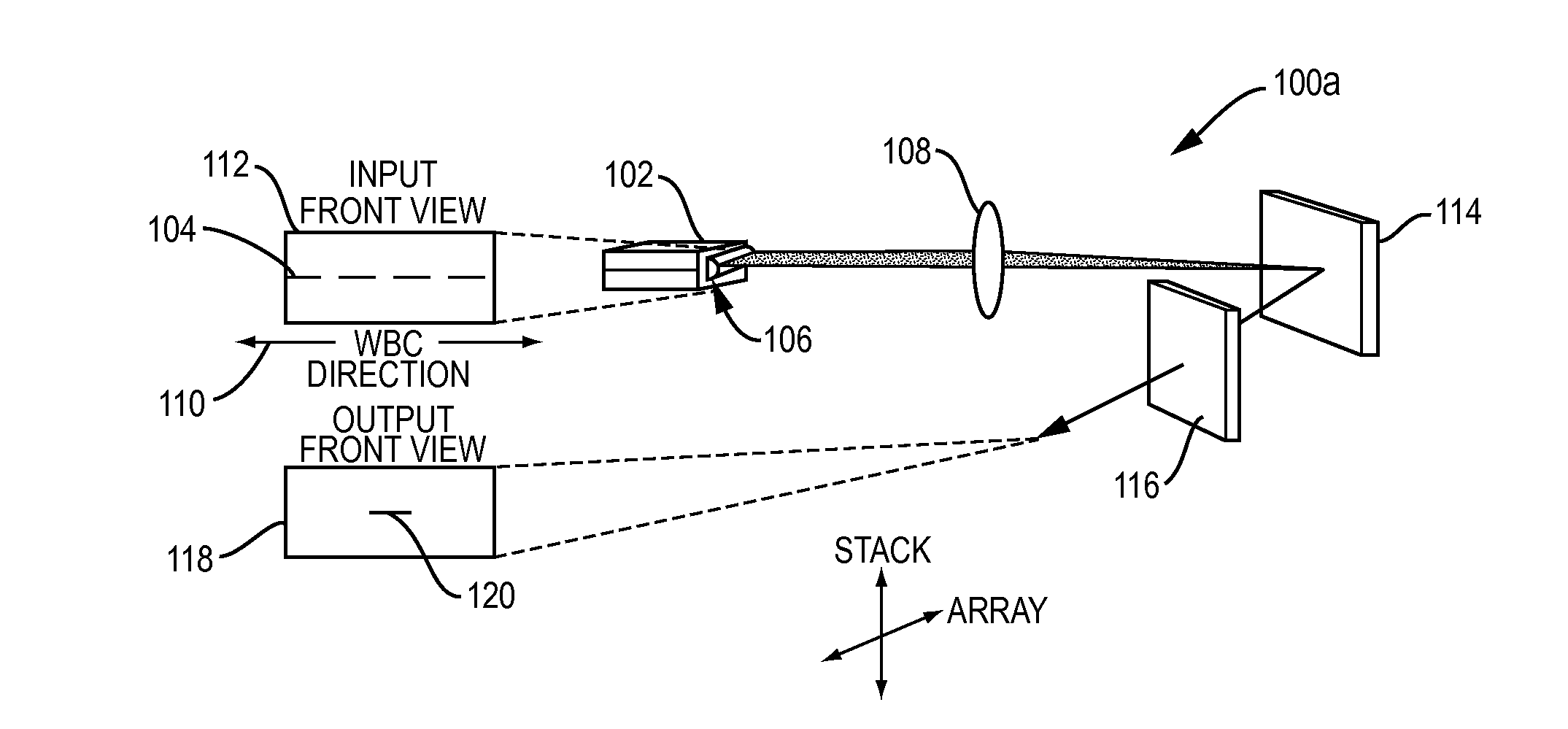
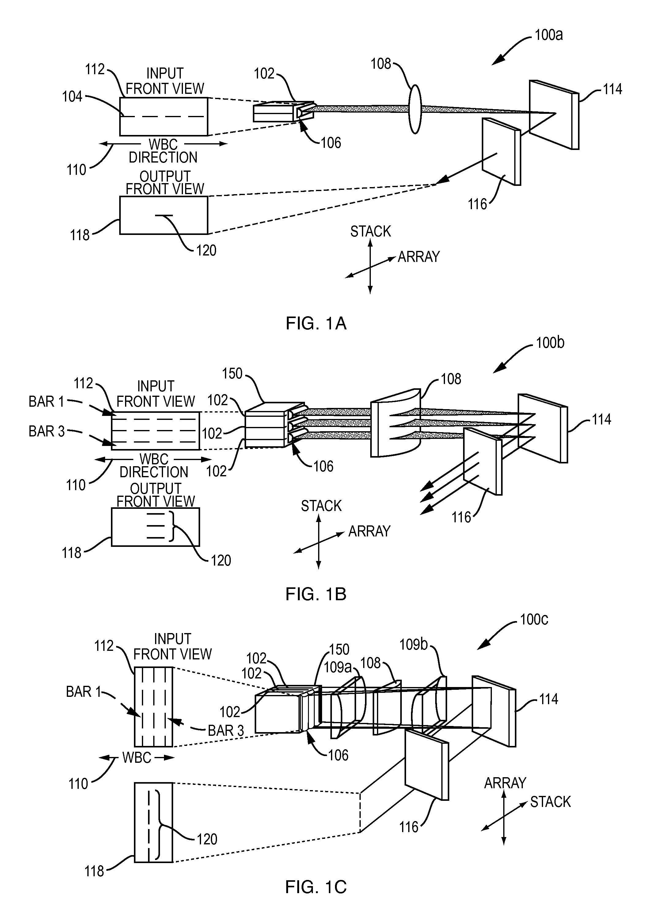
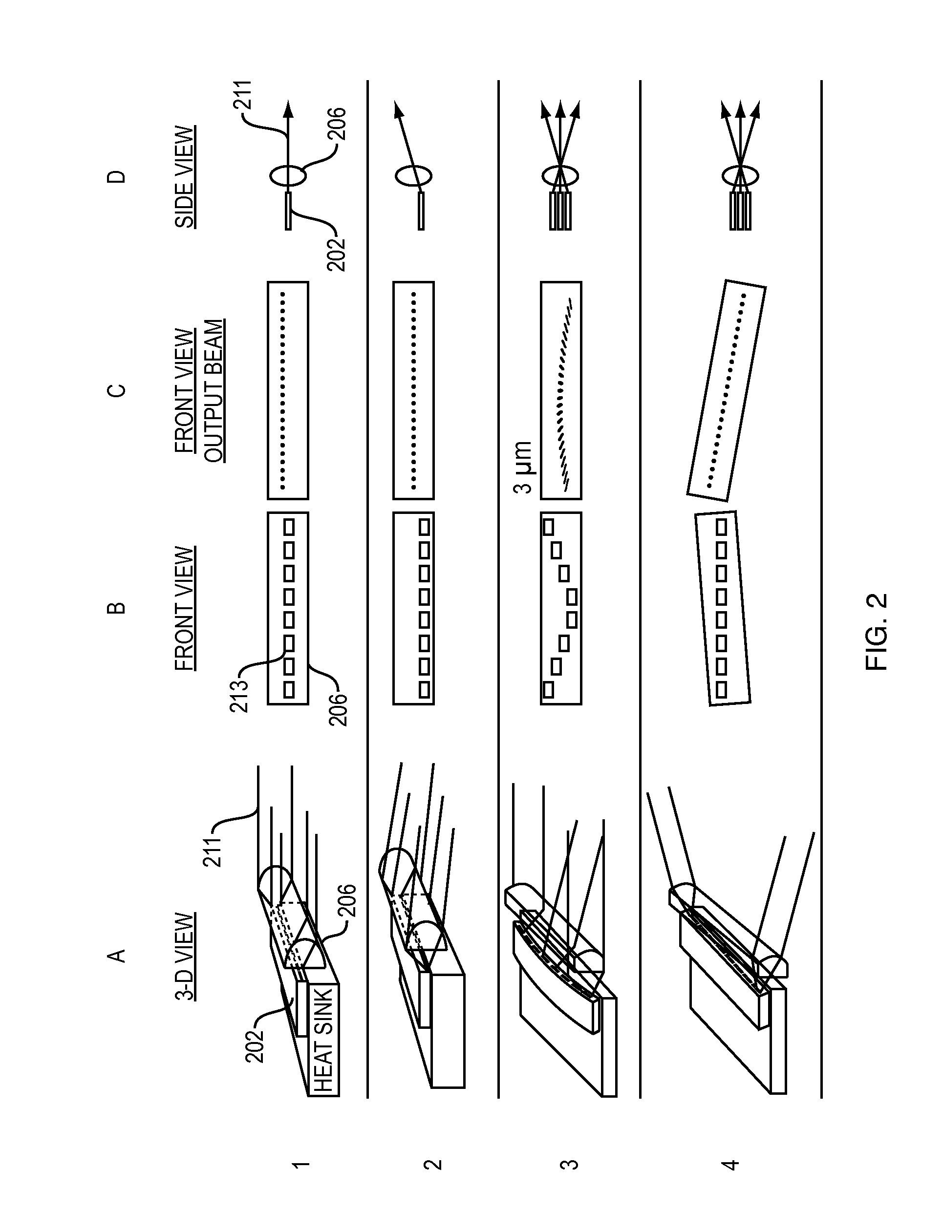
[0027]Embodiments described herein include addressing: 1) manipulating beam profiles through rotation and spatial repositioning techniques in a WBC system, which allows for increasing output power and brightness through combining multiple emitters in a common system. Through the various embodiments and techniques described herein a stabilized, high brightness multi-wavelength output laser system may be achieved.

[0028]The approaches and embodiments described herein may apply to one and two-dimensional beam combining systems along the slow-axis, fast-axis, or other beam combining dimension. For purposes of this application optical elements may refer to any of lenses, mirrors, prisms and the like which redir...


PUM


Abstract

A system and method for reconfiguring a plurality of electromagnetic beams to take advantage of various wavelength beam combining techniques. The reconfiguring of beams includes individual rotation and selective repositioning of one or more beams with respect to beam's original input position.

Description

CROSS-REFERENCE TO RELATED APPLICATIONS[0001]This application is a continuation of U.S. Ser. No. 13 / 042,042 filed Mar. 7, 2011.BACKGROUND OF THE INVENTION[0002]1. Field of the Invention[0003]The present embodiments relate generally to laser systems and more particularly to wavelength beam combining systems and methods.[0004]2. Description of the Prior Art[0005]Wavelength beam combining (WBC) is a method for scaling the output power and brightness from laser diode bars, stacks of diode bars, as well as other lasers arranged in one or two-dimensional array.[0006]WBC methods have been developed to combine beams along the slow dimension of each emitter as well as the fast dimension of each emitter. As such, the system is more sensitive to imperfections in the optical gain elements. Furthermore, when broad-area optical gain elements are used the spectral utilization is poor. In some cases beam combining is performed along the stacking dimension. In such implementations the WBC stabilizin...

Claims


Application Information

Patent Timeline
IPC IPC(8): G02B27/10
CPCG02B27/1006G02B27/0905H01S3/06733H01S3/0675H01S3/094053H01S3/094057H01S3/09408H01S3/094096H01S3/09415H01S3/1618H01S3/175H01S3/176H01S5/0057H01S5/4012H01S5/405H01S5/4062H01S5/4087H01S2301/03G02B19/0057G02B19/009G02B19/0028G02B19/0014G02B23/04G02B27/14
Inventor CHANN, BIENHUANG, ROBIN
Owner TERADIODE
Why Eureka
Try Eureka