Communication system

a communication system and communication technology, applied in the field of communication systems, can solve problems such as interference from user equipment to local nodes, radio link failure (rlf), and collision risk of rach, and achieve the effects of reducing interference, improving the throughput of the entire communication system, and large uplink transmission power

Inactive Publication Date: 2014-02-06
MITSUBISHI ELECTRIC CORP
View PDF5 Cites 29 Cited by
  • Summary
  • Abstract
  • Description
  • Claims
  • Application Information

AI Technical Summary

Benefits of technology

[0108]According to the communication system of the present invention, the communication quality in a case where a large-scale communication device and a small-scale communication device are installed to coexist can be improved, to thereby improve the throughput of the entire communication system. Further, an effect of relatively large uplink transmission power from the terminal device to the large-scale communication dev

Problems solved by technology

The RACH involves a collision risk.
Re-establishment is triggered when the PCell results in a radio link failure (RLF).
In this case, an interference may occur from a user equipment to the local node.
As described above, an imbalance in link, that is, a link imbalance occurs.
When a link imbalance occurs, an interference occurs from the user equipment to the RRH due to relatively large uplink transmission power from the user equip

Method used


Image

  • Communication system
  • Communication system
  • Communication system

Examples


first embodiment

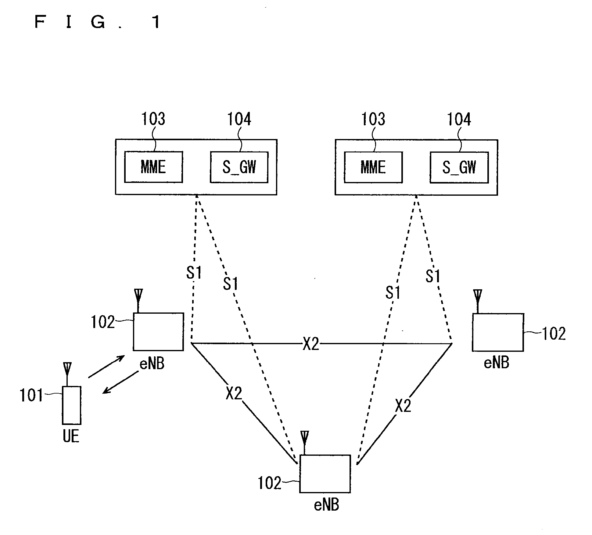
[0138]FIG. 7 is a block diagram showing an overall configuration of an LTE mobile communication system, which is currently under discussion of 3GPP. Currently, an overall system configuration including closed subscriber group (CSG) cells (Home-eNodeBs (Home-eNB; HeNB) of E-UTRAN, Home-NB (HNB) of UTRAN) and non-CSG cells (eNodeB (eNB) of E-UTRAN, NodeB (NB) of UTRAN, and BSS of GERAN) is studied in 3GPP and, as to E-UTRAN, the configuration as shown in FIG. 7 is proposed (see Chapter 4.6.1 of Non-Patent Document 1).

[0139]FIG. 7 is described. A user terminal device (hereinafter, referred to as “user equipment” or “UE”) 71 is capable of performing radio communication with a base station device (hereinafter, referred to as “base station”) 72 and transmits / receives signals through radio communication. The user terminal device is equivalent to a communication terminal device. The base stations 72 are classified into an eNB 72-1 that is a macro cell and a Home-eNB 72-2 that is a local nod...

second embodiment

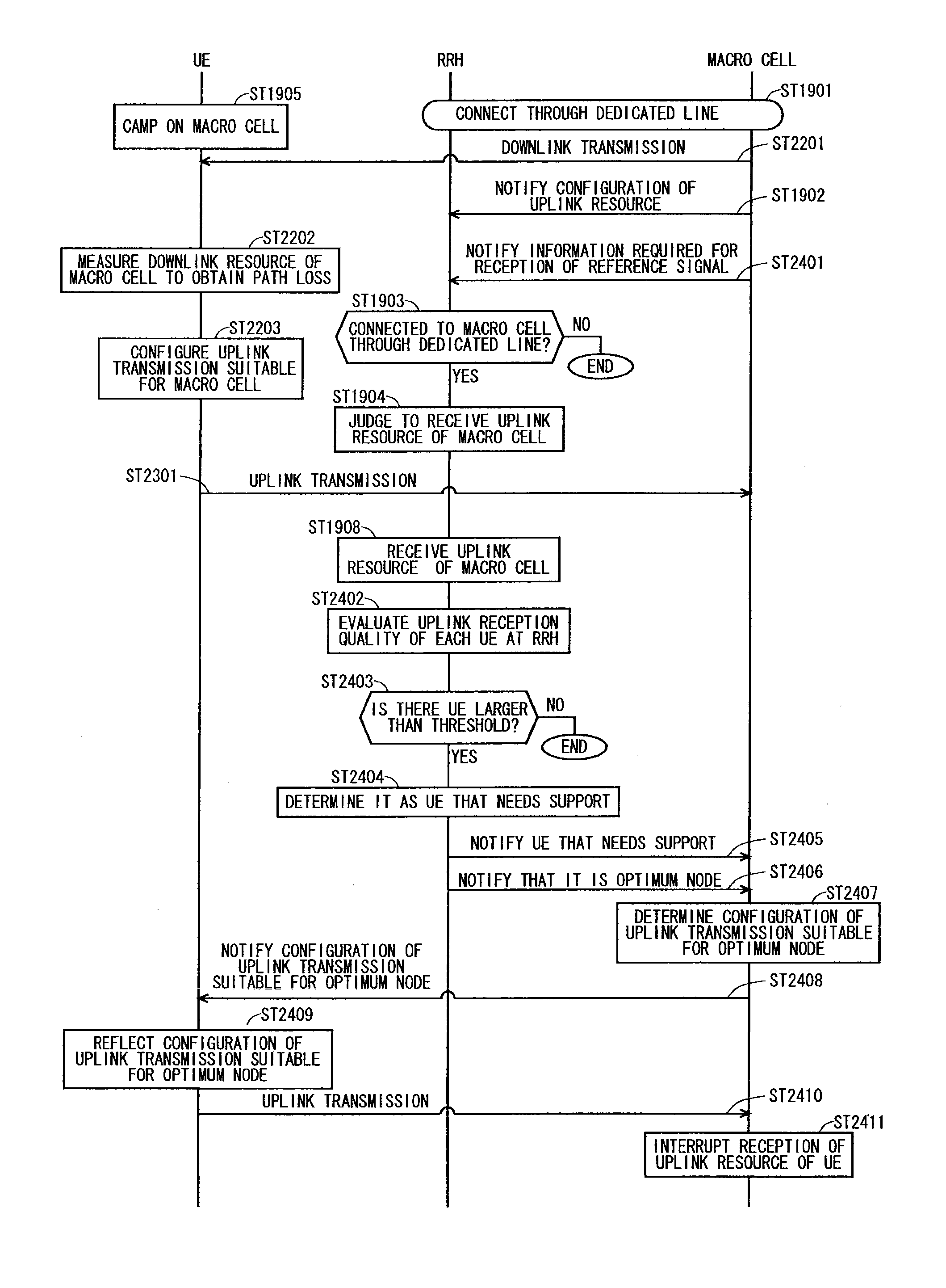
[0303]A problem to be solved in a second embodiment is described below. Even in cases where the first embodiment and the first modification of the first embodiment are used, another problem may occur. This problem is described with reference to FIG. 17 described above.

[0304]As described above, in the area Z between the point A and point B shown in FIG. 17, a link between the user equipment (UE) and RRH 1603 is good in uplink, and a link between the UE and macro cell 1601 is good in downlink. An imbalance in link, that is, link imbalance occurs as described above.

[0305]In the conventional technique, the user equipment camps on a cell having the best downlink reception quality, and thereafter, starts communication with the cell as required (see Non-Patent Document 3). Accordingly, in the conventional technique, a situation in which an optimum link is not used in uplink communication occurs in, for example, the area Z between the point A and point B shown in FIG. 17. In this case, the ...

third embodiment

[0436]A third embodiment discloses another solution to the same problem as that of the first embodiment and second embodiment described above. The solution in the third embodiment is described below. Carrier aggregation is performed using an uplink component carrier of an optimum node in uplink without using downlink component carriers thereof. Alternatively, carrier aggregation is performed using a downlink component carrier and an uplink component carrier of a macro cell and an uplink component carrier of the optimum node in uplink. Still alternatively, a component carrier of the optimum node for uplink is used in uplink of a secondary cell (SCell).

[0437]The concept of the solution in the third embodiment is described with reference to FIG. 25. FIG. 25 is a diagram for describing the concept of the solution in the third embodiment.

[0438]A macro cell 2501 includes a DL_CC1 indicated by reference numeral 2502 and a DL_CC2 indicated by reference numeral 2503 as downlink component car...


PUM


Abstract

A communication system improving the communication quality in a case where a plurality of communication devices having different sizes of ranges coexist, in which communication with a terminal device is possible, to thereby improve an entire throughput. In a case where a remote radio head (RRH) is installed in a coverage of a macro cell, an uplink resource transmitted from a user equipment (UE) to the macro cell, that is, an uplink carrier frequency band UL1 of the macro cell is received not only by the macro cell but also by the RRH. Then, the macro cell combines a reception signal regarding the uplink resource of the macro cell, which has been received by the macro cell, and a reception signal regarding the uplink resource of the macro cell, which has been received by the RRH.

Description

TECHNICAL FIELD[0001]The present invention relates to a communication system in which a base station device performs radio communication with a plurality of communication terminal devices.BACKGROUND ART[0002]Commercial service of a wideband code division multiple access (W-CDMA) system among so-called third-generation communication systems has been offered in Japan since 2001. In addition, high speed downlink packet access (HSDPA) service for achieving higher-speed data transmission using a downlink has been offered by adding a channel for packet transmission (high speed-downlink shared channel (HS-DSCH)) to the downlink (dedicated data channel, dedicated control channel). Further, in order to increase the speed of data transmission in an uplink direction, service of a high speed uplink packet access (HSUPA) system has been offered. W-CDMA is a communication system defined by the 3rd generation partnership project (3GPP) that is the standard organization regarding the mobile communi...

Claims


Application Information

Patent Timeline
IPC IPC(8): H04W72/04
CPCH04W72/0426H04B7/022H04W52/146H04W52/244H04W52/40H04B17/327H04W56/0045H04W72/27H04W72/04H04W52/143
Inventor MAEDA, MIHOMOCHIZUKI, MITSURU
Owner MITSUBISHI ELECTRIC CORP
Why Eureka
Try Eureka