
Flexible heat and moisture transfer system

a technology of heat and moisture transfer and flexible heat, which is applied in indirect heat exchangers, lighting and heating apparatuses, heating types, etc., can solve the problems of loss of heat energy, corresponding reduction in heating or cooling efficiency of the system, and inability to perform moisture exchang

Inactive Publication Date: 2014-02-13
ARCHITECTURAL APPL P C
View PDF26 Cites 12 Cited by
  • Summary
  • Abstract
  • Description
  • Claims
  • Application Information

AI Technical Summary

Benefits of technology

The patent describes a flexible heat and moisture exchanger that can be used to control the temperature and humidity in an enclosed space. The exchanger has a flexible outer shell and a flexible, water vapor-permeable barrier that separates the interior of the exchanger into multiple subchannels. The exchanger can receive two air streams simultaneously and can be easily disconnected from the air streams and ported to a different location. The technical effects of this invention include improved control over the temperature and humidity in enclosed spaces, as well as improved portability and flexibility in the installation and placement of the heat and moisture exchanger.

Problems solved by technology

A corresponding portion of the air which has already been heated or cooled to the desired supply conditions must be exhausted, resulting in a loss of heat energy and a corresponding reduction in the heating or cooling efficiency of the system conditioning the air in the spaces.
Good heat exchange is generally possible with these materials, but moisture exchange cannot easily be performed.
However, water absorbed by the paper from condensation, rain, or moisture present in the air can lead to corrosion, deformation, and mildew growth, and, hence, deterioration of the paper exchange film.
The nature of moisture exchange requires a very large surface area in contact with the gas stream, and, consequently, total heat exchangers are often very large in size when compared to heat-only exchangers.
A disadvantage of such porous composite film is that it also permits the exchange of substantial amounts of air between the gas streams, as well as particles, cigarette smoke, cooking odors, harmful fumes, and the like.
From the point of view of building indoor air quality, this is undesirable.
In order to prevent this contamination of make-up air, the pore volume of a porous film is preferably no more than about 15%, which is difficult and expensive to achieve uniformly.
Furthermore, a porous film made to a thickness of 5 to 40 micrometers in order to improve heat exchange efficiency tears easily and is difficult to handle.

Method used


Image

  • Flexible heat and moisture transfer system
  • Flexible heat and moisture transfer system
  • Flexible heat and moisture transfer system

Examples


Embodiment Construction

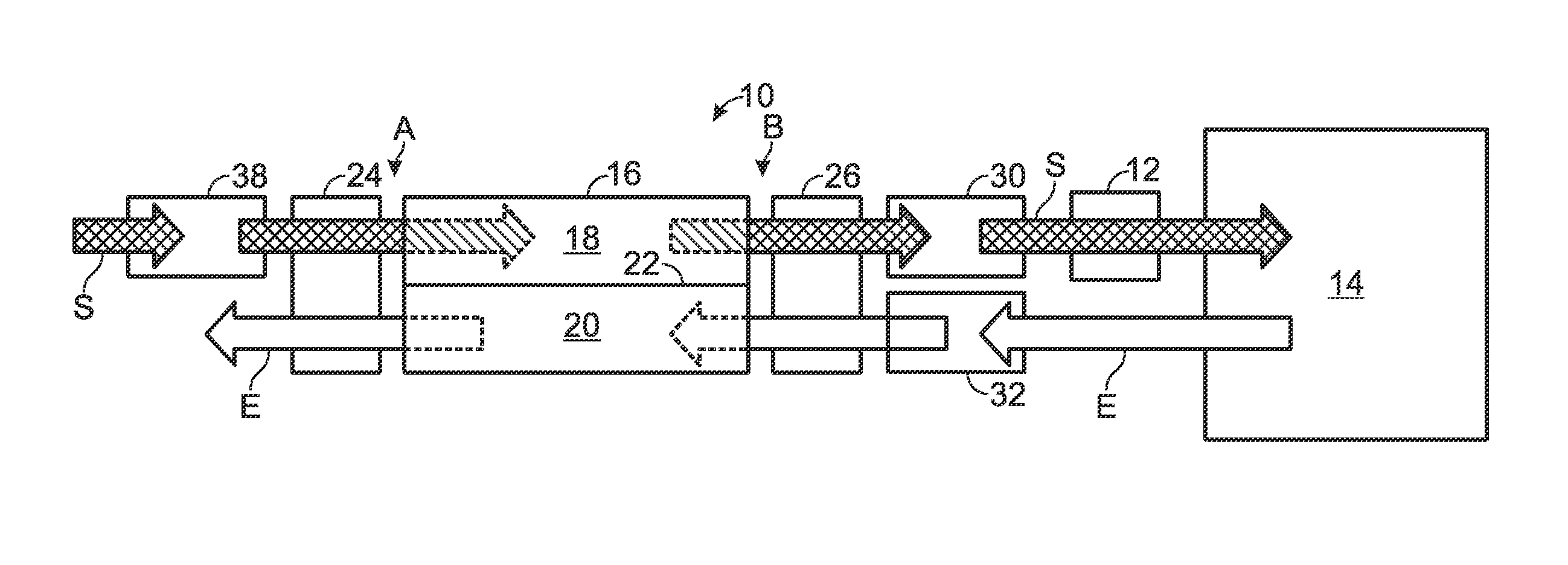
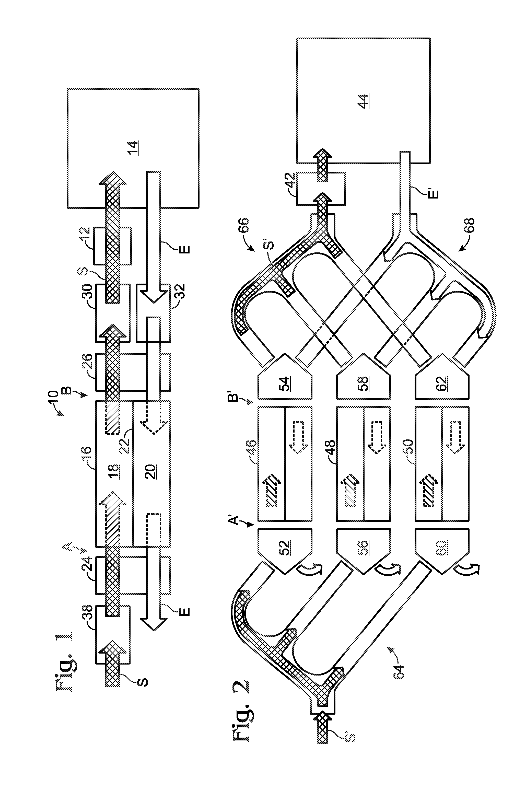
[0018]An efficient heat and moisture exchange apparatus is described herein which will not contaminate make-up air, and which has excellent heat exchange efficiency, high moisture exchange capability, and serves as a barrier to air flow between exhaust and makeup air streams. Furthermore, the exchanger described in the present disclosure is suitable for use with lightweight temporary, portable, and permanent structures in which the mechanical conditioning and ventilation equipment may not be located within or atop the structure but may instead stand on the ground adjacent the structure. In many of these cases, the structures may be pliable and flexible to enable packing and transport, such as tents, that are not amenable to large-scale rigid elements. Accordingly, a flexible heat and moisture exchanger is described that can be used in the operation of these flexible, mobile structures but can also be packed and transported easily with them.

[0019]Illustrative flexible heat and moistu...


PUM

PropertyMeasurementUnit
emissivityaaaaaaaaaa
thicknessaaaaaaaaaa
emissivityaaaaaaaaaa

Abstract

A heat and moisture transfer system may include a flexible heat and moisture exchanger in fluid communication with an environment control unit and an enclosed space. The flexible heat and moisture exchanger may include at least one flexible water vapor-permeable membrane, and may be configured to pass air streams simultaneously in different directions in adjacent subchannels formed by the membrane.

Description

CROSS-REFERENCE TO RELATED APPLICATIONS[0001]This application claims priority to U.S. Provisional Patent Application Ser. No. 61 / 682,232, filed Aug. 11, 2012, which is hereby incorporated by reference.INTRODUCTION[0002]Mechanically heated or cooled and ventilated buildings and other structures require that some portion of fresh make-up air be added continuously to the total volume of circulated air to keep the space fresh, comfortable, and healthy. A corresponding portion of the air which has already been heated or cooled to the desired supply conditions must be exhausted, resulting in a loss of heat energy and a corresponding reduction in the heating or cooling efficiency of the system conditioning the air in the spaces. Heat exchangers are sometimes used in the exhaust air and makeup airflow paths of these systems such that heat is transferred between the two airstreams according to the temperature differential, leaving less cooling or heating to be performed by the mechanical sys...

Claims


Application Information

Patent Timeline
Patent Type & Authority Applications(United States)
IPC IPC(8): F28D15/00
CPCF28D15/00F24F3/147F24F12/006F28D21/0015F28F21/065F28F2255/02Y02B30/56
Inventor BRESHEARS, JOHN EDWARD
Owner ARCHITECTURAL APPL P C
Learn More