
Cutting Method And Cutting Stage Of Toughened Glass

a cutting method and cutting technology, applied in the direction of paper/cardboard containers, manufacturing tools, containers, etc., can solve the problems of high breakage ratio of half-finished products, difficulty in mechanically cutting the contour of toughened glass or machine, and low productivity, so as to reduce the central tension inside the cutting portion, improve cost competitiveness, and avoid cracking or chipping. , the effect of reducing the central tension

Active Publication Date: 2014-02-13
SAMSUNG CORNING PRECISION MATERIALS CO LTD
View PDF5 Cites 53 Cited by
  • Summary
  • Abstract
  • Description
  • Claims
  • Application Information

AI Technical Summary

Benefits of technology

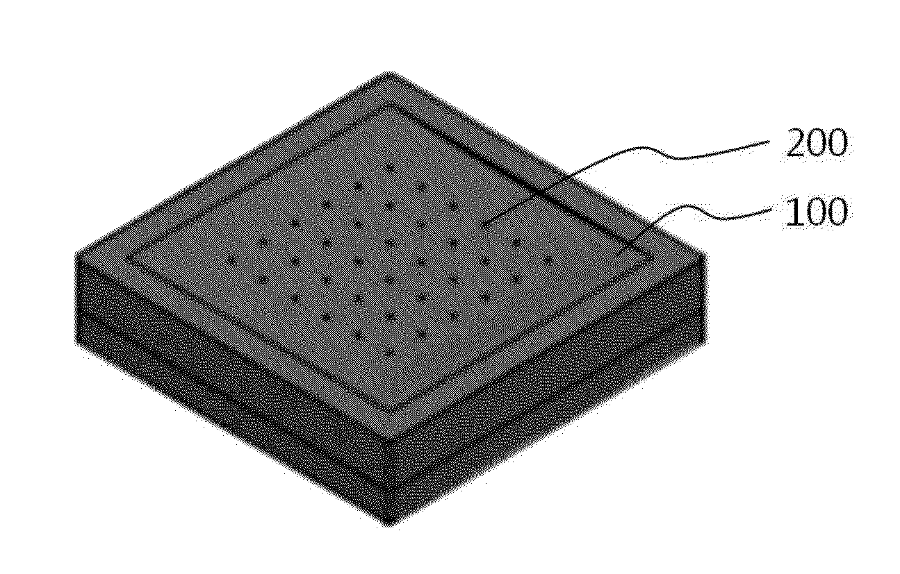
The present invention provides a cutting method and cutting stage for toughened glass that allows for safe and effective cutting without causing cracks or chips. This is achieved by reducing the central tension inside the cutting portion of the glass through a process of concavely bending and forming a median crack. The cutting is done in a simple and cost-effective way, improving competitiveness.

Problems solved by technology

It is difficult to mechanically cut the toughened glass or machine its contour after toughening due to its characteristics and the absence of techniques for machining them.
However, this method has the drawback of low productivity since production costs such as personnel expenses are high and the breakage ratio of half-finished products is high due to a large number of manual processes.
Furthermore, the importance of the yield is increasing due to the increasing size of mobile displays.
It is becoming more difficult to apply this method of toughening a piece of glass after cutting and machining it to a mass production process.
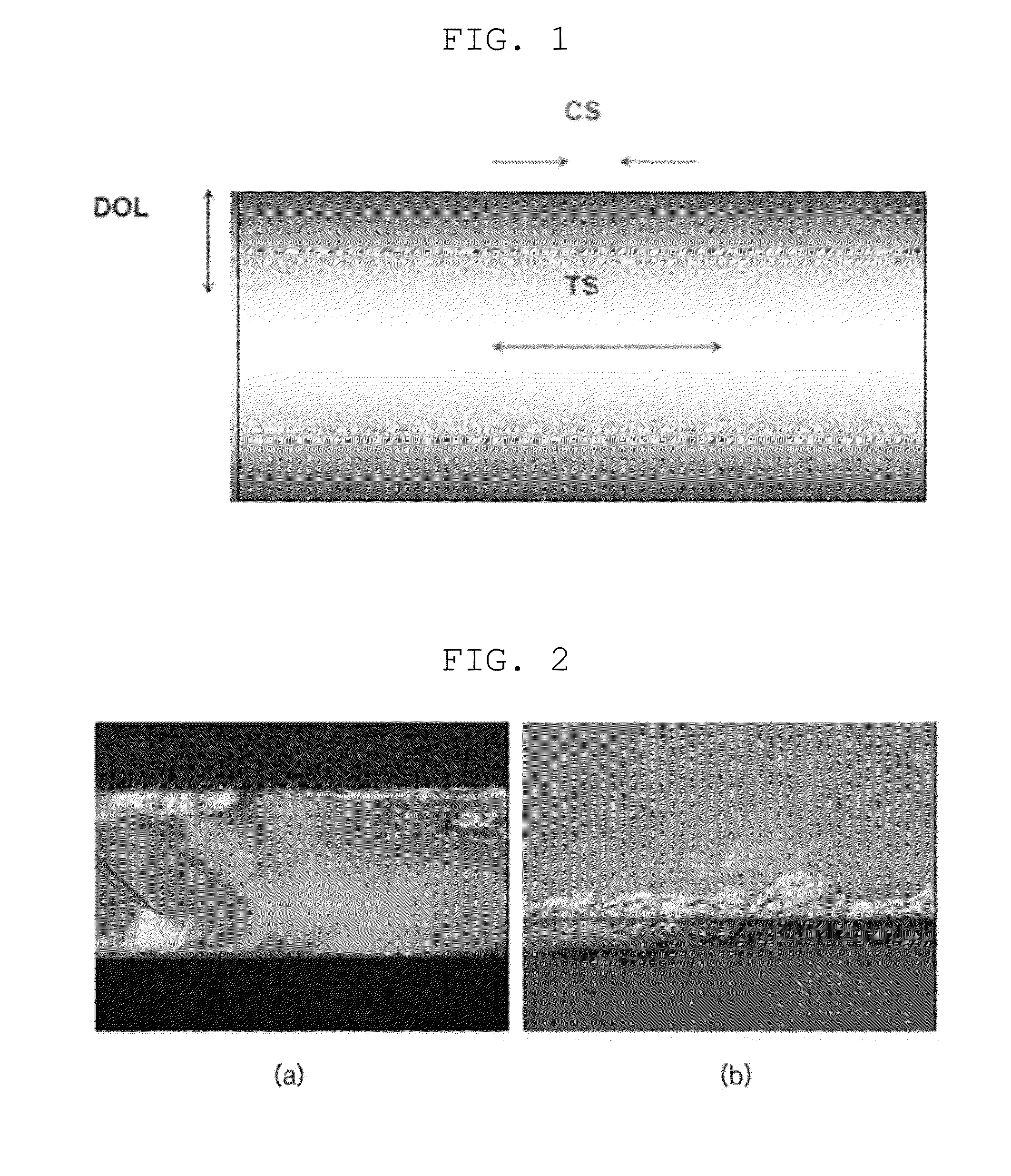
However, as for a chemically-toughened glass that has a depth of layer (DOL) of about 20 μm or greater and a surface compressive stress of 600 MPa or greater, it is generally impossible to cut the glass using a mechanical wheel.
However, such a toughened glass also has a problem in that the direction of scribing cannot be controlled since crack-out occurs during wheel scribing when the thickness of the glass is 0.7 t or less, even though the glass can be wheel-scribed at a thickness of 1.0 t or greater.
However, this laser-based cutting technology has drawbacks in that process conditions are very complicated and equipment is very expensive.
Therefore, this technology is not appropriate to a manufacturing process that requires a low cost and a high yield.

Method used


Image

  • Cutting Method And Cutting Stage Of Toughened Glass
  • Cutting Method And Cutting Stage Of Toughened Glass
  • Cutting Method And Cutting Stage Of Toughened Glass

Examples


Embodiment Construction

[0038]Reference will now be made in detail to a cutting method and cutting stage of toughened glass according to the present invention, embodiments of which are illustrated in the accompanying drawings and described below, so that a person having ordinary skill in the art to which the present invention relates can easily put the present invention into practice.

[0039]Throughout this document, reference should be made to the drawings, in which the same reference numerals and signs are used throughout the different drawings to designate the same or similar components. In the following description of the present invention, detailed descriptions of known functions and components incorporated herein will be omitted when they may make the subject matter of the present invention unclear.

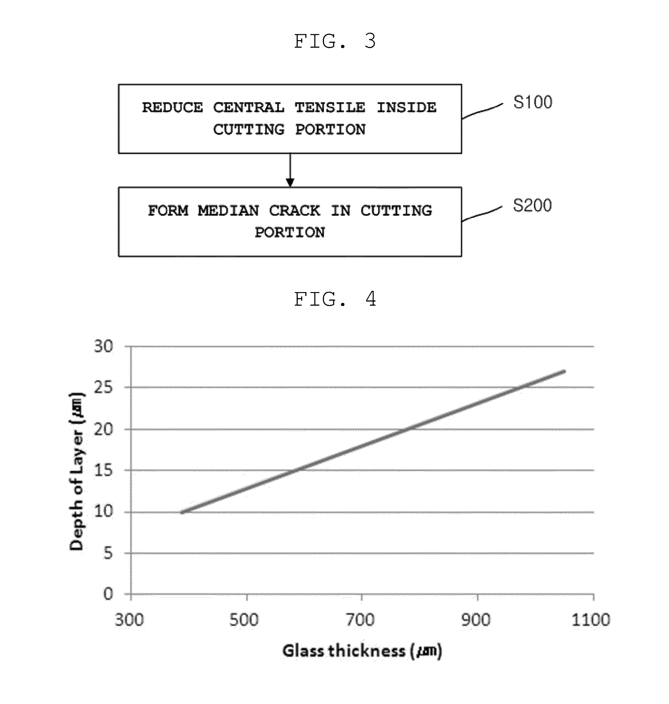
[0040]FIG. 3 is a schematic flowchart showing a cutting method for toughened glass according to an embodiment of the present invention.

[0041]Referring to FIG. 3, the cutting method for toughened glass accord...


PUM

PropertyMeasurementUnit
Fractionaaaaaaaaaa
Thicknessaaaaaaaaaa
Pressureaaaaaaaaaa

Abstract

A cutting method and cutting stage of toughened glass with which a piece of toughened glass is divided into unit pieces of toughened glass. The cutting method cuts a piece of toughened glass which is strengthened by forming a compressive stress in the surface of a raw glass plate. The method includes the steps of reducing the central tension inside a cutting portion of the piece of toughened glass that is to be cut by concavely bending the cutting portion; and cutting the piece of toughened glass by forming a median crack in the cutting portion.

Description

CROSS REFERENCE TO RELATED APPLICATION[0001]The present application claims priority from Korean Patent Application Number 10-2012-0086823 filed on Aug. 8, 2012, the entire contents of which are incorporated herein for all purposes by this reference.BACKGROUND OF THE INVENTION[0002]1. Field of the Invention[0003]The present invention relates to a cutting method and cutting stage of toughened glass, and more particularly, to a cutting method and cutting stage of toughened glass with which a piece of toughened glass is divided into unit pieces of toughened glass.[0004]2. Description of Related Art[0005]Glass products are indispensable components in a variety of technological and industrial fields, involving image and optical equipment, such as monitors, cameras, video tape recorders (VTRs), mobile phones and the like, transportation equipment, such as vehicles, various types of tableware, construction facilities, and the like. Accordingly, glass products having a variety of physical pr...

Claims


Application Information

Patent Timeline
IPC IPC(8): C03B33/033C03B33/03
CPCC03B33/03C03B33/033B65G2249/04Y10T83/0341Y10T83/343Y10T225/12Y02P40/57C03B33/02C03B33/10
Inventor LEE, JAE CHANG
Owner SAMSUNG CORNING PRECISION MATERIALS CO LTD
Learn More