Self-contained renewable battery charger

a self-contained, renewable technology, applied in the direction of secondary cell servicing/maintenance, electrochemical generators, greenhouse gas reduction, etc., can solve the problems of inconvenient installation of permanent charging stations, inability to provide permanent charging stations, and limited access to additional recharge stations. , to achieve the effect of preventing tipping, maximizing sunlight incidence, and increasing ballas

Active Publication Date: 2014-02-13
BEAM GLOBAL
View PDF6 Cites 24 Cited by
  • Summary
  • Abstract
  • Description
  • Claims
  • Application Information

AI Technical Summary

Benefits of technology

[0010]Also for the present invention, a tracking mechanism can be integrated into the column for moving the solar array to adjust the solar array orientation and maximize the incidence of sunlight on the photovoltaic modules. More specifically, the tracking mechanism can be positioned to interconnect a stationary portion of the column with the solar array. With this arrangement, the tracking mechanism can be used to selectively move the solar array relative to the stationary docking pad. In some cases, the solar array movements can be in accordance with a predetermined cycle that is developed based on the position and movements of the sun.
[0011]To assist in transporting the portable unit, a pivot mechanism can be provided between the column and docking pad to selectively pivot the solar array between a deployed configuration and a stowed configuration. In the deployed configuration, the solar array extends from the column to a free end and overlays the base. In the deployed configuration, the solar array and docking pad are arranged to provide ballast to the portable unit to prevent tipping in adverse weather conditions. The ballast against tipping is further increased by the weight and arrangement of the storage batteries in the docking pad compartment. In the stowed configuration, the solar array is folded about the pivot point such that the free end of the solar array is adjacent to the docking pad. Once adjacent to the docking pad, the free end can be attached to the docking pad to secure the solar array for transport.

Problems solved by technology

Unfortunately, access to additional recharge stations is somewhat limited at the present time in most areas.
In some instances, the temporary location requiring a charging station may not have ready access to the electrical grid.
In other instances, the cost of providing a permanently installed charging station may be prohibitive or the lead-time associated with a permanent installation may be unsatisfactory.

Method used


Image

  • Self-contained renewable battery charger
  • Self-contained renewable battery charger
  • Self-contained renewable battery charger

Examples


Embodiment Construction

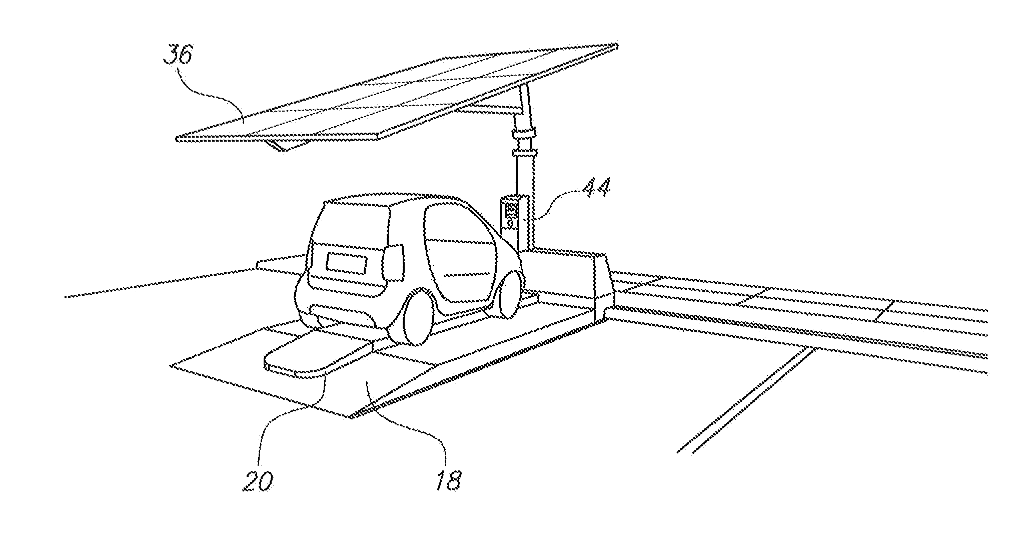
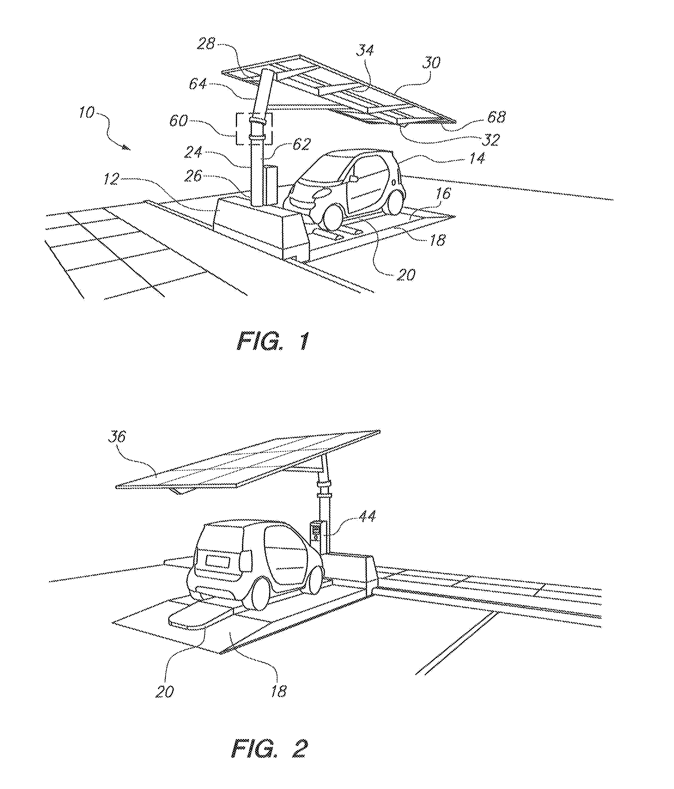
[0019]Referring initially to FIG. 1, a system in accordance with the present invention is shown and is generally designated 10. As shown, the system 10 includes a portable unit 12 for charging an electric vehicle 14. As described herein, the portable unit 12 can be transported, after assembly, to a location such as the parking lot shown, where it can operate to charge an electric vehicle 14 without necessarily being connected to the electrical grid (not shown) or another source of electrical power.

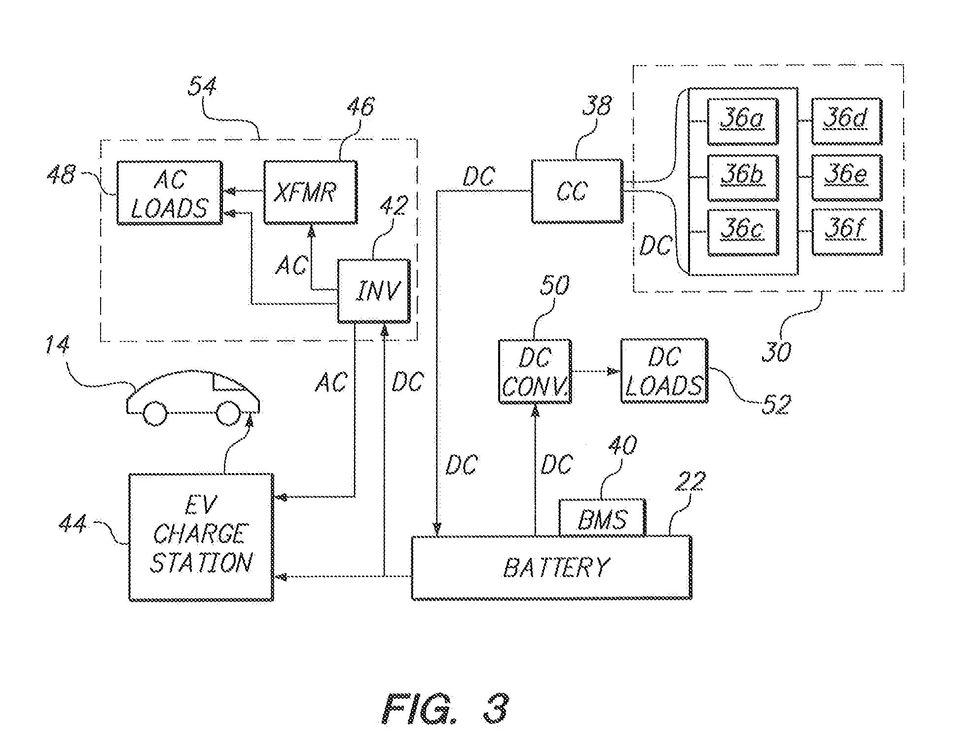
[0020]Cross-referencing FIGS. 1 and 2, it can be seen that the portable unit 12 includes a moveable docking pad 16 having a base 18 and a compartment 20 for holding at least one storage battery 22 and electronics (see FIG. 3). It is to be appreciated that the term ‘battery’ as used herein includes a battery bank having one or more batteries and / or battery cells that are operatively connected together. As shown, the base 18 of the docking pad 16 may be of suitable construction to support th...


PUM

PropertyMeasurementUnit
energyaaaaaaaaaa
electrical energyaaaaaaaaaa
currentaaaaaaaaaa

Abstract

A self-contained, portable unit for charging a battery of an electric vehicle is disclosed. The portable unit includes a moveable docking pad that has a generally flat, horizontal base and is formed with a compartment for holding at least one storage battery. The first end of a column is mounted onto the docking pad and oriented to extend upwardly from the docking pad to a second column end. A solar array is affixed to the second end of the column for deployment over the docking pad. The electric current from the solar array is fed to the storage battery using a charge management system. The battery, in turn, is connected to an EV charge station which produces a charging current to charge the battery of an electric vehicle.

Description

FIELD OF THE INVENTION[0001]The present invention pertains generally to electric charging systems for vehicles and devices. More particularly, the present invention pertains to systems and methods for charging electric vehicles using solar energy. The present invention is particularly, but not exclusively, useful as a portable, self-contained charging system for efficiently storing energy from solar arrays and using the stored energy to charge the batteries of an electric vehicle.BACKGROUND OF THE INVENTION[0002]Electric vehicles (EV), which can include all-electric vehicles and hybrids such as gas / electric vehicles, are growing in popularity among consumers.[0003]These vehicles offer an environmentally friendly alternative to vehicles powered exclusively by petroleum products. In particular, EV's have lower emissions of smog precursor gases, and they emit little to no greenhouse gases which have been linked to ‘global warming’. In addition, as the cost of petroleum products has inc...

Claims


Application Information

Patent Timeline
Patent Type & Authority Applications(United States)
IPC IPC(8): H02J7/35H02J7/00
CPCH02J7/0042H02J7/35H02J7/0044H02S10/40H02S20/32H02S40/38H02J2310/48Y02E10/56Y02E70/30Y10T29/49117
Inventor WHEATLEY, DESMONDSENATORE, PATRICK
Owner BEAM GLOBAL
Why Eureka
Try Eureka