High efficiency solar cells

a solar cell, high-efficiency technology, applied in photovoltaics, electrical equipment, semiconductor devices, etc., can solve the problems of reducing the production cost of semiconductor materials currently used for solar cells, crystalline silicon, etc., and achieve the effect of maximizing the incidence and maximizing the desired energy

Inactive Publication Date: 2006-06-29
GR INTELLECTUAL RESERVE LLC
View PDF9 Cites 2 Cited by
  • Summary
  • Abstract
  • Description
  • Claims
  • Application Information

AI Technical Summary

Benefits of technology

[0009] Another object of the invention is to limit or restrict certain undesirable incident wavelengths of light (and thus certain frequencies and energy levels) from becoming incident upon a solar cell photovoltaic substrate.
[0010] It is another object of the invention to limit or restrict (i.e., minimize) certain destructively interfering (or at least partially destructively interfering) incident wavelengths of light within the photoreactive portion of the solar spectrum from becoming incident upon a solar cell photovoltaic substrate so as to maximize the incidence of constructively interfering (or at least partially constructively interfering) incident wavelengths which, for example, substantially match those wavelengths (e.g., amounts of energy) which cause desirable interactions to occur between the incident light and the solar cell substrate (e.g., excite electrons from a substrate into an appropriate energy collection system on the substrate (e.g., a conductive grid), to produce desirable electrical current). Moreover, the incident light energy can be converted to desirable atomic or molecular energies (e.g., electronic) and thus, for example, further energize the electrons to assist in the production of electrical power.
[0011] It is an object of the invention to determine which particular energies (and thus which particular wavelengths or frequencies) of incident light, within the photoreactive portion of the solar spectrum, are required for any desired solar cell photovoltaic substrate so as to permit predominantly desirable interactions to occur. Desirable interactions include, for example, electrons being excited from one energy level to another to result in current; and providing energy to the electrons which can assist in promoting the electrons to a conduction band to result in current. After determining which energies (and thus which wavelengths or frequencies) are desirable, the invention then substantially restricts the wavelengths or frequencies of undesirable light which are incident upon said substrate, said restricting occurring by utilizing an appropriate filtering technique or light modifying (e.g., shifting, refracting, etc.) technique, and thus maximizing those desirable energies of light which contact or are incident upon a solar cell substrate.

Problems solved by technology

For example, it is relatively expensive to manufacture those semiconductor materials currently utilized for solar cells (e.g., crystalline silicon, amorphous silicon, cadmium sulfide, etc.) into solar panels (e.g., typically, a plurality of combined solar cells electrically connected together) which includes the high costs of forming the solar cell substrate materials themselves, the cost of modifying the substrate materials so that they can become photovoltaic (e.g., doping the semiconductor substrate material to create substrate p / n junctions, etc.), the placement of electron collecting grids on surfaces of the solar cells, manufacturing the solar cells into solar panels, etc.
However, this entire process has historically been relatively inefficient, making the solar cell industry less than ideal.

Method used


Image

  • High efficiency solar cells
  • High efficiency solar cells
  • High efficiency solar cells

Examples


example 1

[0052] This Example demonstrates that the selected blocking of certain small groups or small portions of wavelengths or energies of visible light (e.g., blocking a portion of the photoreactive solar spectrum) can increase the output of a solar cell relative to unblocked visible light incident on the same solar cell. It should be understood that maximum output from solar cells will be achieved from blocking somewhat smaller and more numerous of wavelengths of the photoreactive portion of the visible spectrum but that this Example merely proves the general concept of the invention.

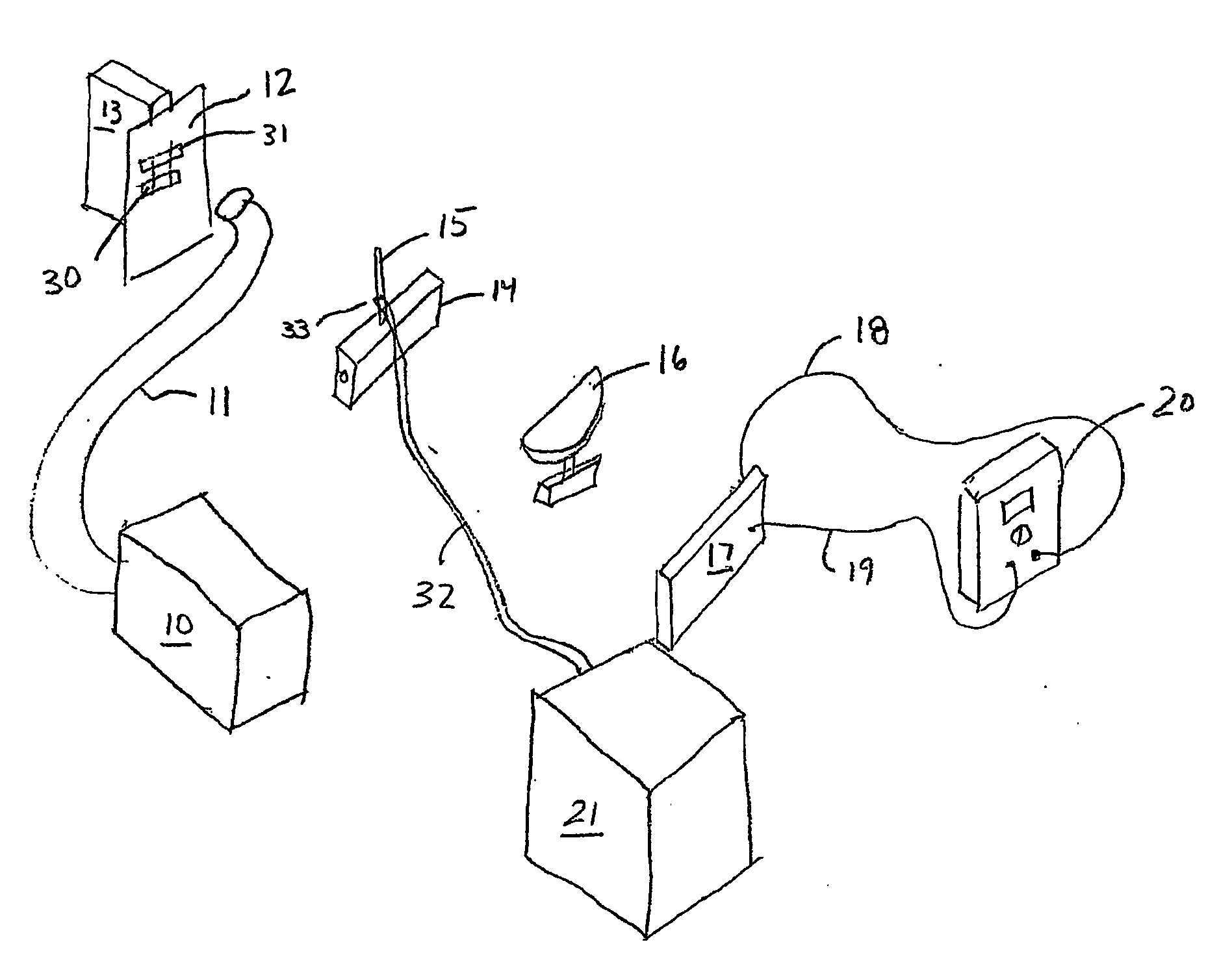
[0053]FIG. 5 shows a schematic of the experimental set-up used in accordance with this Example. A light source 10 known as an IMAGELITE™ from Stockard and Yale provided a suitable light spectrum that was transmitted through the flexible cable 11. The light emitted from the cable 11 was caused to be incident upon both of the separate slits 30 and 31 that were formed into a light opaque member 12. Each of the...


PUM


Abstract

The present invention relates to improvements in solar cell and solar panel photovoltaic materials which cause the solar cells/panels to operate more efficiently. In particular, the present invention focuses primarily on matching or modifying particular incident light energies within the photoreactive portion of the solar spectrum to predetermined energy levels in a solar cell photovoltaic substrate material required to excite, for example, electrons in at least a portion of the substrate material in a desirable manner. The portions (X) and (Y) represent areas where the two waves (1) and (2) have at least partially constructively interfered, and partially destructively interfered, respectively. Depending upon whether the portion (X) corresponds to desirable or undesirable wavelengths, the portion (X) could enhance a positive or negative effect in the substrate material. Similarly, the portion (Y) may correspond to the effective loss of either a positive or negative effect.

Description

FIELD OF THE INVENTION [0001] The present invention relates to improvements in solar cell and solar panel photovoltaic materials which cause the solar cells / panels to operate more efficiently. In particular, the present invention focuses primarily on matching or modifying particular incident light energies (e.g., solar energies) within the photoreactive portion of the solar spectrum to predetermined energy levels in a solar cell photovoltaic substrate material (e.g., a semiconductor material) required to excite, for example, electrons in at least a portion of the substrate material in a desirable manner (e.g., to cause desirable movement of electrons to result in output amperages previously unobtainable). In this regard, for example, energy levels of incident light within the optical or visible light portion of the solar spectrum (i.e., the photoreactive portion of the solar spectrum) and thus, corresponding particular wavelengths or frequencies of incident light, can be at least pa...

Claims


Application Information

Patent Timeline
Patent Type & Authority Applications(United States)
IPC IPC(8): H01L25/00H01LH01L31/04H01L31/052
CPCH01L31/02162H01L31/0547H01L31/0543Y02E10/52
Inventor MORTENSON, MARK G.
Owner GR INTELLECTUAL RESERVE LLC
Why Eureka
Try Eureka