Light emitting diode bulb structure for enhancing heat dissipation efficiency

a technology of light-emitting diodes and bulb structures, which is applied in the direction of lighting and heating apparatus, lighting support devices, light sources, etc., can solve the problems of shortening the life cycle of the overall structure, prone to multiple disposal by manufacturers, and reducing the heat dissipation efficiency of heat-dispersing seats, etc., and achieves the effect of improving the heat dissipation efficiency and high costs

Inactive Publication Date: 2014-02-13
CHUANG SHENG YI
View PDF1 Cites 26 Cited by
  • Summary
  • Abstract
  • Description
  • Claims
  • Application Information

AI Technical Summary

Benefits of technology

[0014]Therefore a primary object of the present invention is to overcome issues of high costs and inferior heat dissipation efficiency of a heat dissipation seat in a conventional LED bulb.
[0028]The LED bulb structure for enhancing heat dissipation efficiency offers advantages of lower production costs, minimal hazards of an electric shock for a user and enhanced heat dissipation efficiency.
[0029]The heat dissipating body of the present invention is made of a mixture of a plastic material and ceramic powder and formed through injection molding. Compared to a conventional heat dissipating body made of a metal material, the heat dissipating body of the present invention offers lower production costs.
[0030]As previously stated, the heat dissipating body of the present invention is made of a mixture from a plastic material and ceramic power, and is lower in electric conductivity compared to a conventional heat dissipation module made of a metal material. Therefore, hazards of an electric shock caused by an electric leakage of circuit components in an LED are minimized for a user.
[0031]Moreover, the heat conducting body of the present invention comprises a plurality of heat conducting fins extended radially and outwardly from the surface of the heat conducting portion. Then the heat dissipating body is formed on the heat conducting body through injection molding, and comprises a plurality of heat dissipating fins disposed on the surface thereof correspondingly to the heat conducting fins, such that the heat dissipating fins completely encase the heat conducting fins therein. More specifically, the contact area between heat conducting body and the heat dissipating body is expanded via the heat conducting fins, and a surface area of the heat dissipating body exposed to the exterior is further increased by the heat dissipating fins. Consequently, heat absorbed by the heat conducting body from the light source substrate can be quickly conducted to the heat dissipating body, and then dissipated through the heat dissipating fins disposed on the surface of the heat dissipating body.

Problems solved by technology

However, by summarizing technical issues to be solved by the prior arts, an LED bulb encounters the following technical issues.
First of all, to increase brightness of a bulb, manufacturers are prone to dispose multiple LED chips on a light source substrate having a small area.
In the event that heat generated by the chips cannot be efficiently dissipated, the chips may be degraded due to high temperature to shorten life cycle of the overall structure.
However, the heat dissipating fins are made of a costly metal material that contradicts with an expected low cost of a consumable.
However, an extremely high voltage nevertheless breaks through the insulation structure such that the LED bulb still fails a high-voltage test.
Thus the limited contact area results in degradation of heat conduction efficiency between the heat dissipating sheet and the lamp socket.
In addition, as the lamp socket is made of a non-metal material, it also decreases the heat dissipation efficiency.
However, as the conductive member has good electric conductivity, in the event that a high voltage is applied to the LED lamp device, a user could easily be exposed to hazards of an electric shock.
However, the issue of an insufficient contact area between the heat dissipation module and the heat dissipating fins yet remains.

Method used


Image

  • Light emitting diode bulb structure for enhancing heat dissipation efficiency
  • Light emitting diode bulb structure for enhancing heat dissipation efficiency
  • Light emitting diode bulb structure for enhancing heat dissipation efficiency

Examples


Embodiment Construction

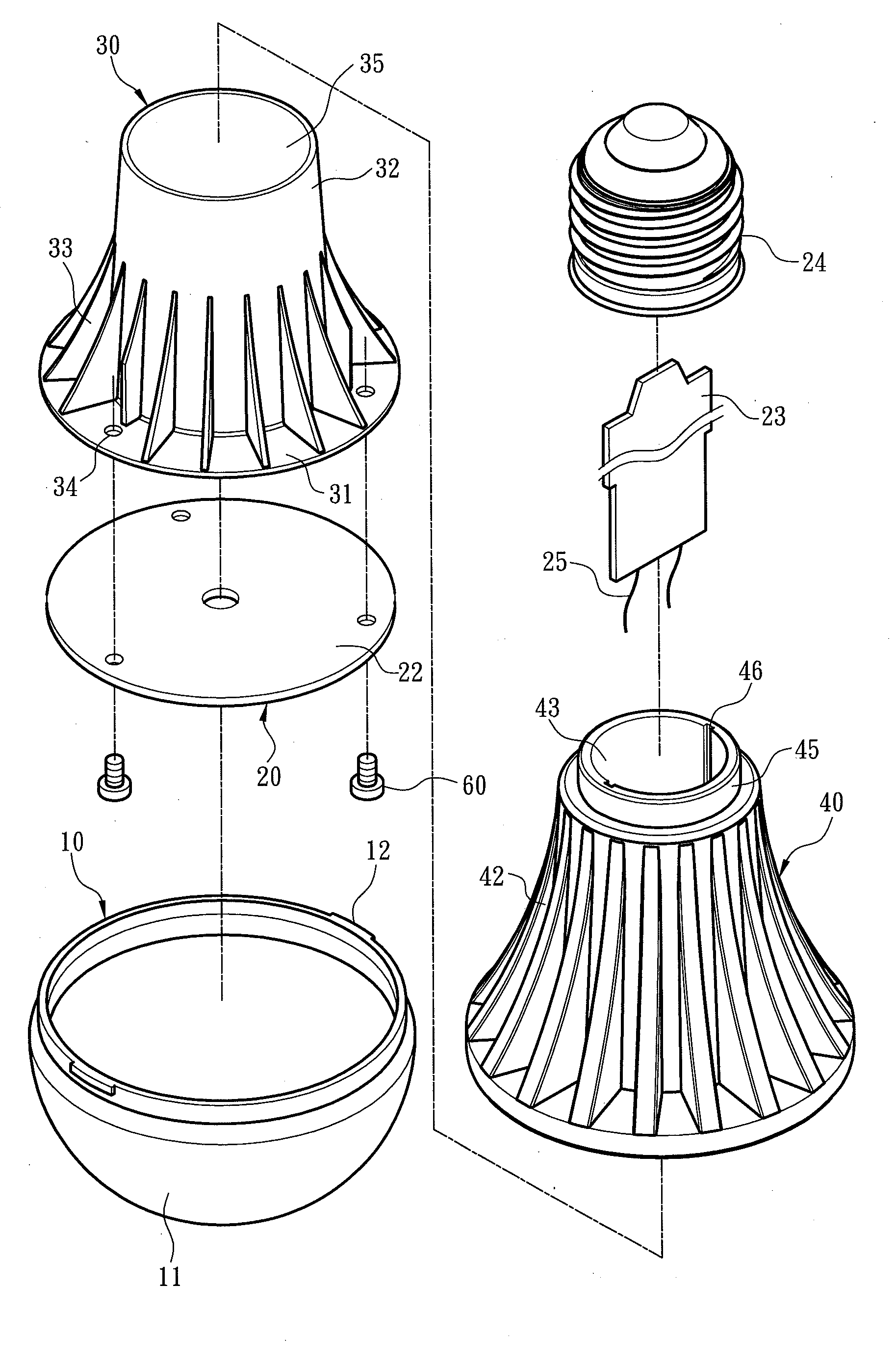
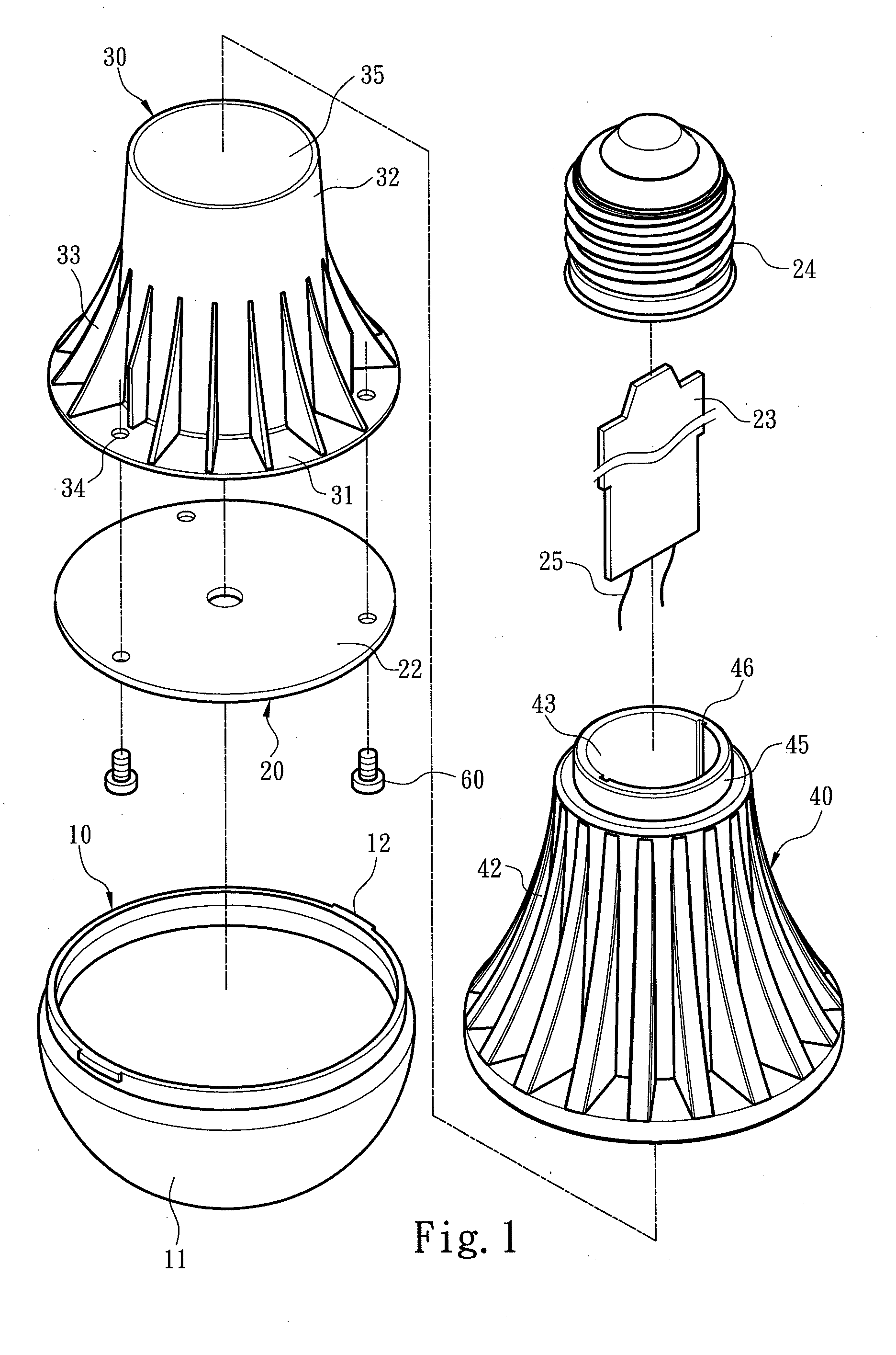
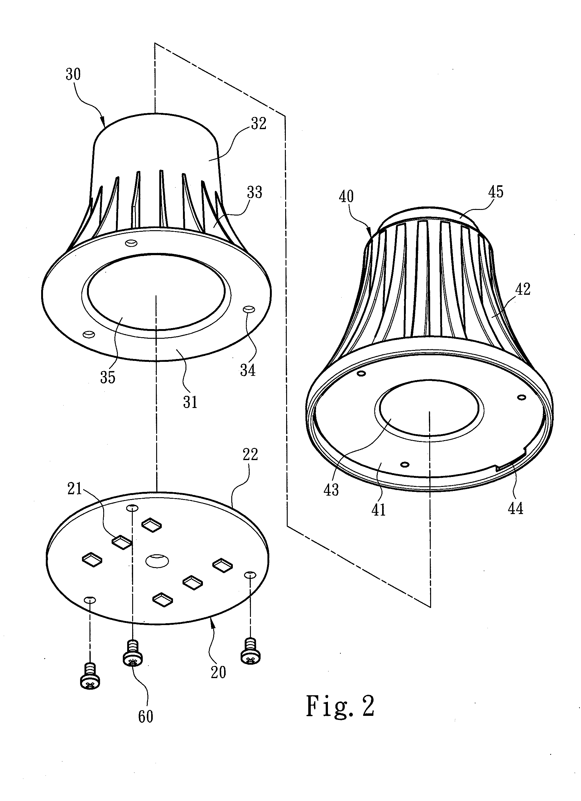
[0037]FIGS. 1 and 2 respectively show first and second exploded views of a light emitting diode (LED) bulb structure according to an embodiment of the present invention. Referring to FIGS. 1 and 2, the LED bulb structure for enhancing heat dissipation efficiency comprises a lamp shell 10, a light emitting assembly 20, a heat conducting body 30 and a heat dissipating body 40. The light emitting assembly 20 comprises a light source substrate 22 disposed in the lamp shell 10 and carrying at least one light emitting element 21, a circuit board 23 electrically connected to the light source substrate 22, and a power connection socket 24 receiving an external power and electrically connected to the circuit board 23.

[0038]The lamp shell 10 comprises a transmittance portion 11 and at least one wedging portion 12 extended from the transmittance portion 11. The heat dissipating body 40 comprises a carrying plane 41 corresponding to the light source substrate 22, and at least one positioning po...


PUM


Abstract

A light emitting diode (LED) bulb structure includes a lamp shell, a light emitting assembly, a heat conducting body and a heat dissipating body. The light emitting assembly includes a light source substrate carrying at least one light emitting element. The heat conducting body includes a heat collecting portion contacting the light source substrate, a heat conducting portion connecting to the heat collecting portion, and multiple heat conducting fins extended radially and outwardly from the heat conducting portion. The heat dissipating body is formed on the heat conducting body through injection molding and includes multiple heat dissipating fins disposed on the surface thereof correspondingly to the heat conducting fins such that the heat conducting fins are encased therein. Accordingly, heat generated by the light source substrate is absorbed by the heat collecting portion and then conducted from the heat conducting fins to the heat dissipating fins for dissipation.

Description

FIELD OF THE INVENTION[0001]The present invention relates to a light emitting diode (LED) lamp device, and particularly to an LED bulb structure for enhancing heat dissipation efficiency.BACKGROUND OF THE INVENTION[0002]A light emitting diode (LED) is a semiconductor electronic element that is enabled to illuminate by electric energy. In an LED, rather than heating a tungsten wire to incandescence by a high current and high resistance, energy released from combining electrons and holes in the semiconductor is utilized as optic energy. Thus, compared to a conventional tungsten light bulb, an LED has advantages of being power saving, long in life cycle and high in brightness. Among various lamp devices using LEDs as light emitting elements, an LED bulb has the most preferred practicability. That is to say in addition to having a lamp shell similar to that of a conventional incandescent bulb as well as a power connection socket, an LED bulb further has benefits of an LED compared to a ...

Claims


Application Information

Patent Timeline
Patent Type & Authority Applications(United States)
IPC IPC(8): F21V29/00
CPCF21V29/2262F21V29/713F21V29/773F21K9/232F21Y2115/10
Inventor CHUANG, SHENG-YI
Owner CHUANG SHENG YI
Why Eureka
Try Eureka