Plasmon generator and thermally-assisted magnetic recording head having the same

a technology of thermally assisted magnetic recording and generator, which is applied in the direction of instruments, nuclear engineering, transportation and packaging, etc., can solve the problems of reducing the volume, reducing the thermal stability of magnetization in the magnetic nanoparticle, and becoming impossible to wri

Active Publication Date: 2014-02-13
TDK CORPARATION
View PDF3 Cites 37 Cited by
  • Summary
  • Abstract
  • Description
  • Claims
  • Application Information

AI Technical Summary

Benefits of technology

[0030]In order to solve the subjects, a plasmon-generator of the present invention is one includes a surface plasmon mode coupling portion that is coupled with light in a surface plasmon mode, a plasmon propagation part that propagates surface plasmon from the coupling portion, and a near-field light generating end surface that is positioned in a distal end part on the propagation part and that generates near-field light. The plasmon-generator includes a first configuration member including the near-field light generating end surface and a second configuration member joined and integrated with the first configuration member and not including the near-field light generating end surface. The first configuration member is configured to contain Au as a primary component and to contain any one or more elements selected from a group of Co, Fe, Sb, Nb, Zr, Ti, Hf, and Ta, and is configured so that a content percentage X1 of the contained element is within a range between 0.2 at % or more and 2.0 at % or less, and the second configuration member is configured from Au.

Problems solved by technology

However, there is a problem that reducing the magnetic nanoparticles in size leads to a decrease in the volume of the magnetic nanoparticles, resulting in a decrease in thermal stability of magnetization in the magnetic nanoparticles.
As a result, when the anisotropic magnetic field of the recording layer of the magnetic recording medium exceeds an acceptable value determined from the upper limit of the writing magnetic field intensity, it becomes impossible to write.
In the case when the heat generation inside the plasmon-generator is large, there is a threat not only that the magnetic head deforms (for example, protrusion of a tip part from the ABS) but also that the plasmon-generator itself may lose its shape due to migration of atoms of the material configuring the plasmon-generator.
Accordingly, there is a concern that the head reliability is significantly affected.
That is, in the case when the plasmon-generator deforms due to the heat generation, there is a threat that a preferred characteristic (heat application ability) is not obtained and a head characteristic is deteriorated.
However, among the materials, Cu is unsuitable for a wafer process and manufacture process in manufacturing the magnetic head since Cu has corrosion against alkali resolution.
In addition, Al is unsuitable for the magnetic head with many processes exposing in the atmosphere since Al has corrosion against alkali resolution and at the same time the surface thereof oxidizes easily.
However, there is a threat that Ag oxidizes and the optical property deteriorates since the film surfaces of the Ag system materials are exposed in the atmosphere under a high temperature environment for the magnetic head and wafer process usage purpose.
However, the Au system materials have poor heat resistance and may deform when heat is applied since the Au system materials themselves are soft and migrate easily.
Only with a simple method in which the dopant is added to the entire plasmon-generator simply formed by Au, the degree of heat generation in the element due to the addition tends to become larger.
In the above-discussed situation, it is difficult to say that optimization of a configuration of the plasmon-generator is achieved.

Method used


Image

  • Plasmon generator and thermally-assisted magnetic recording head having the same
  • Plasmon generator and thermally-assisted magnetic recording head having the same
  • Plasmon generator and thermally-assisted magnetic recording head having the same

Examples


example

[0146]Specific examples are described and further detailed description regarding the present invention will be given below.

first example

[0147]Description of an example regarding the composition of the first configuration member will be given below.

[0148]First, various types of first configuration member samples in a predetermined shape were made by respectively adding 0.5 at % of Co, Nb, Ti, and Zr as additive elements in Au matrixes.

[0149]For each of the samples, an annealing treatment was performed at 250° C. for three hours. After the annealing treatment, a surface roughness Ra of each of the samples was measured as well as a degree of enlargement of a grain size and presence of aggregation of each of the samples were observed by atomic force microscope (AFM) observation.

[0150]Note, the presence of aggregation means a state where a grain size enlarges remarkably, that is, a state where a grain of which size is significantly larger than sizes of surrounding particles exists.

[0151]Table 1, which is described below, illustrates the result.

TABLE 1(Ra, Enlargement of Grain Size andAggregation after Adding 0.5 at %)Sur...

second example

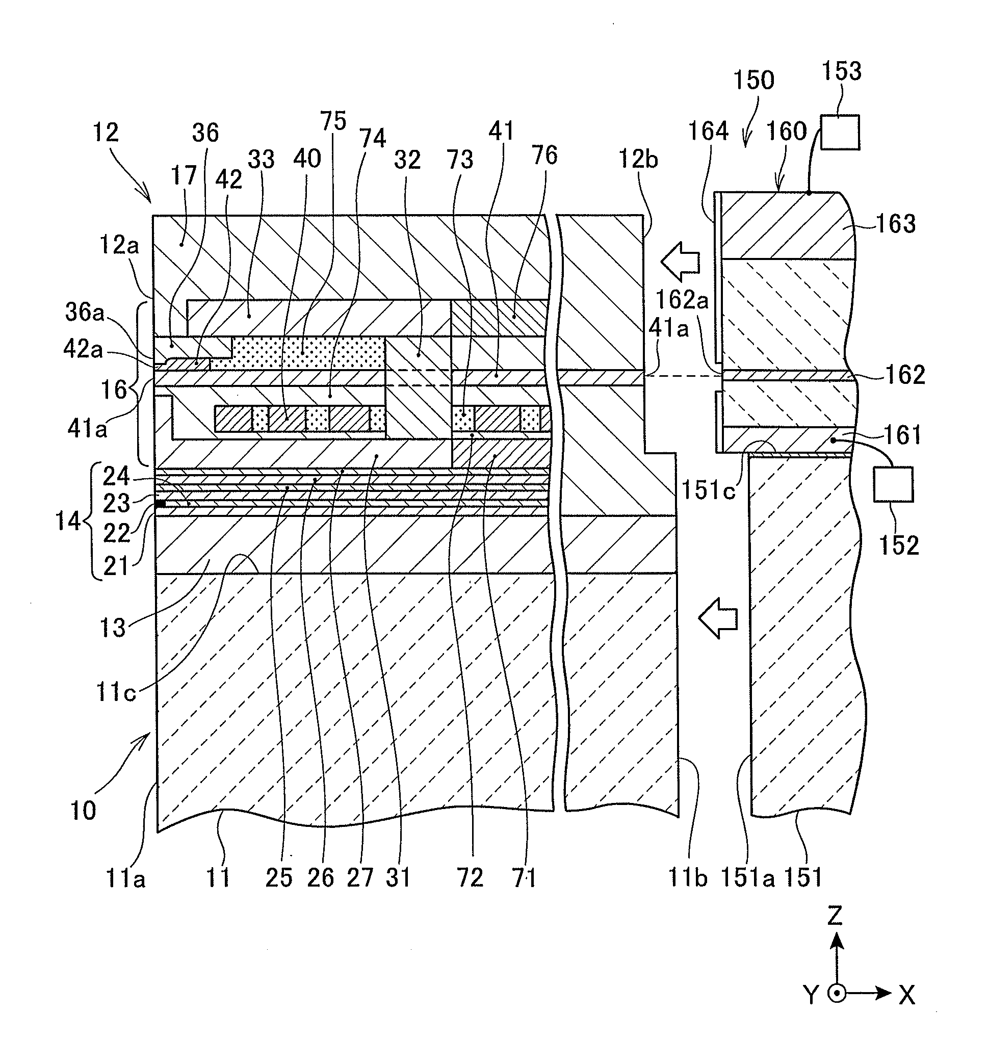
[0158]Next, the first configuration member composed of Au as a primary component and contenting 1.0 at % of Co and the second configuration member composed of an Au simple substance were used, and the plasmon-generator 42 (first example sample) according to the first embodiment as illustrated in FIGS. 6-8 and the plasmon-generator 42 (second example sample) according to the second embodiment as illustrated in FIGS. 9-11 were made. In addition, as a comparative example, a plasmon-generator of the comparative example (comparative example sample), which has the same shape as described above and all region were configured from Au containing 1.0 at % of Co, was made.

[0159]The three types of samples were used and left in a high temperature chamber (environmental temperature 300° C.) for 24 hours and deformation degrees of the plasmon-generators were evaluated. It was observed that realization levels of an effect suppressing the deformation of the plasmon-generators were excellent in the f...


PUM

PropertyMeasurementUnit
thicknessaaaaaaaaaa
thicknessaaaaaaaaaa
thicknessaaaaaaaaaa

Abstract

A plasmon-generator of the invention is configured to include a first configuration member including a near-field light generating end surface; and a second configuration member joined and integrated with the first configuration member and not including the near-field light generating end surface. The first configuration member is configured to contain Au as a primary component and to contain any one or more elements selected from a group of Co, Fe, Sb, Nb, Zr, Ti, Hf, and Ta, and is configured so that a content percentage X1 of the contained element is within a range between 0.2 at % or more and 2.0 at % or less. Thereby, thermostability, optical characteristic, and the process stability are satisfied. Also, heat dissipation and heat generation suppression effect are extremely superior.

Description

BACKGROUND OF THE INVENTION[0001]1. Field of the Invention[0002]The present invention relates to a plasmon-generator that generates near-field light, a thermally-assisted magnetic recording head that irradiates the near-field light to a magnetic recording medium to decrease an anisotropic magnetic field (coercive force) of the magnetic recording medium and then records data, and a head gimbal assembly and a magnetic recording device to which the head is used.[0003]2. Description of the Related Art[0004]In the field of magnetic recording using a magnetic head and a magnetic recording medium, further performance improvements of thin film magnetic heads and magnetic recording media have been demanded in conjunction with a growth of high recording density of magnetic disk devices. For the thin film magnetic heads, composite type thin film magnetic heads that are configured with a configuration in which a magnetoresistive (MR) element for reading and an electromagnetic transducer element...

Claims


Application Information

Patent Timeline
Patent Type & Authority Applications(United States)
IPC IPC(8): H01S3/00G11B13/04
CPCG11B5/314G11B5/6088G11B2005/0021Y10T428/1171Y10T428/1193G02B5/008G02B6/1226G11B5/3133G11B13/08
Inventor HIRATA, KEIHOSOI, RYOKAWAMORI, KEITAROPPONGI, TETSUYA
Owner TDK CORPARATION
Why Eureka
Try Eureka