Gas turbine engine heat exchangers and methods of assembling the same

a technology of heat exchanger and gas turbine engine, which is applied in the direction of lighting and heating equipment, process and machine control, instruments, etc., can solve the problems of fluid flow congeal, raise the temperature of the engine system to unacceptable levels,

Inactive Publication Date: 2014-02-13
UNISON INDUSTRIES
View PDF3 Cites 39 Cited by
  • Summary
  • Abstract
  • Description
  • Claims
  • Application Information

AI Technical Summary

Benefits of technology

[0006]Accordingly, there exists a need for a heat exchanger that prevents t

Problems solved by technology

During engine operation, significant heat is produced which raises the temperature of engine systems to unacceptable levels.
Furthermore, when the bypass valve is disengaged to allow flo

Method used


Image

  • Gas turbine engine heat exchangers and methods of assembling the same
  • Gas turbine engine heat exchangers and methods of assembling the same
  • Gas turbine engine heat exchangers and methods of assembling the same

Examples


Embodiment Construction

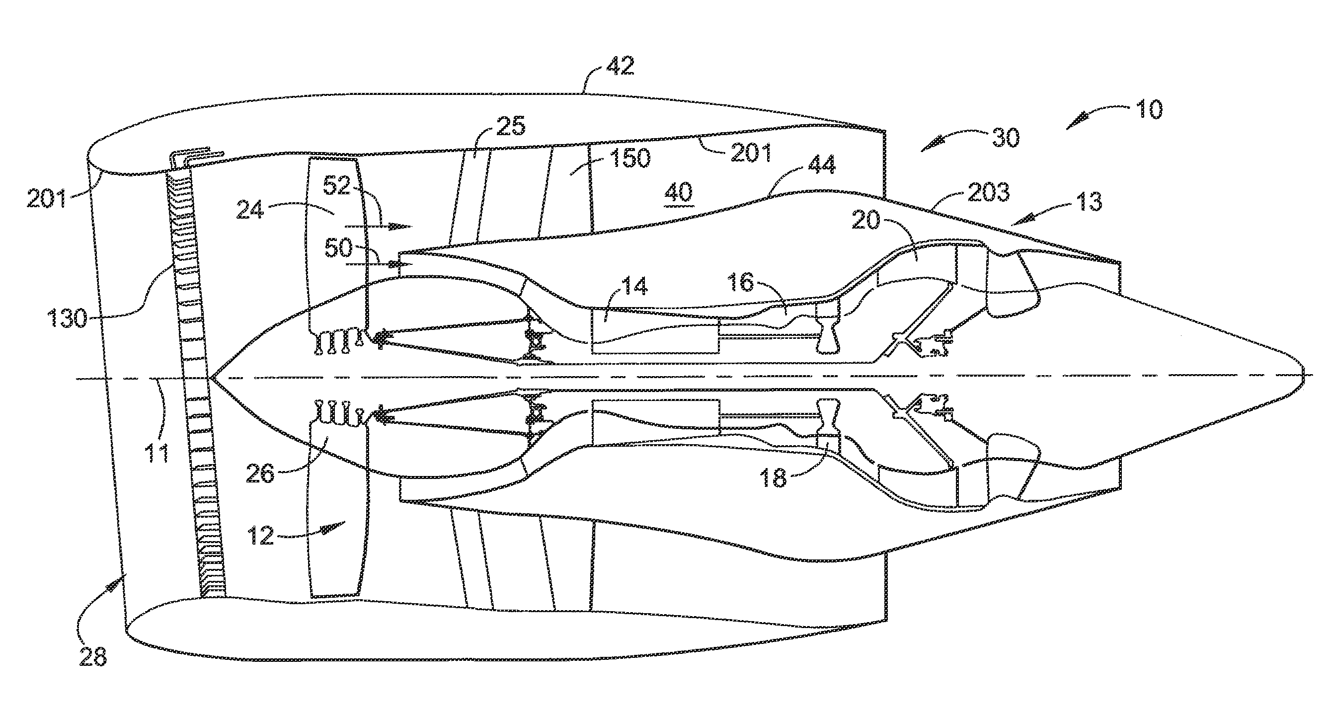
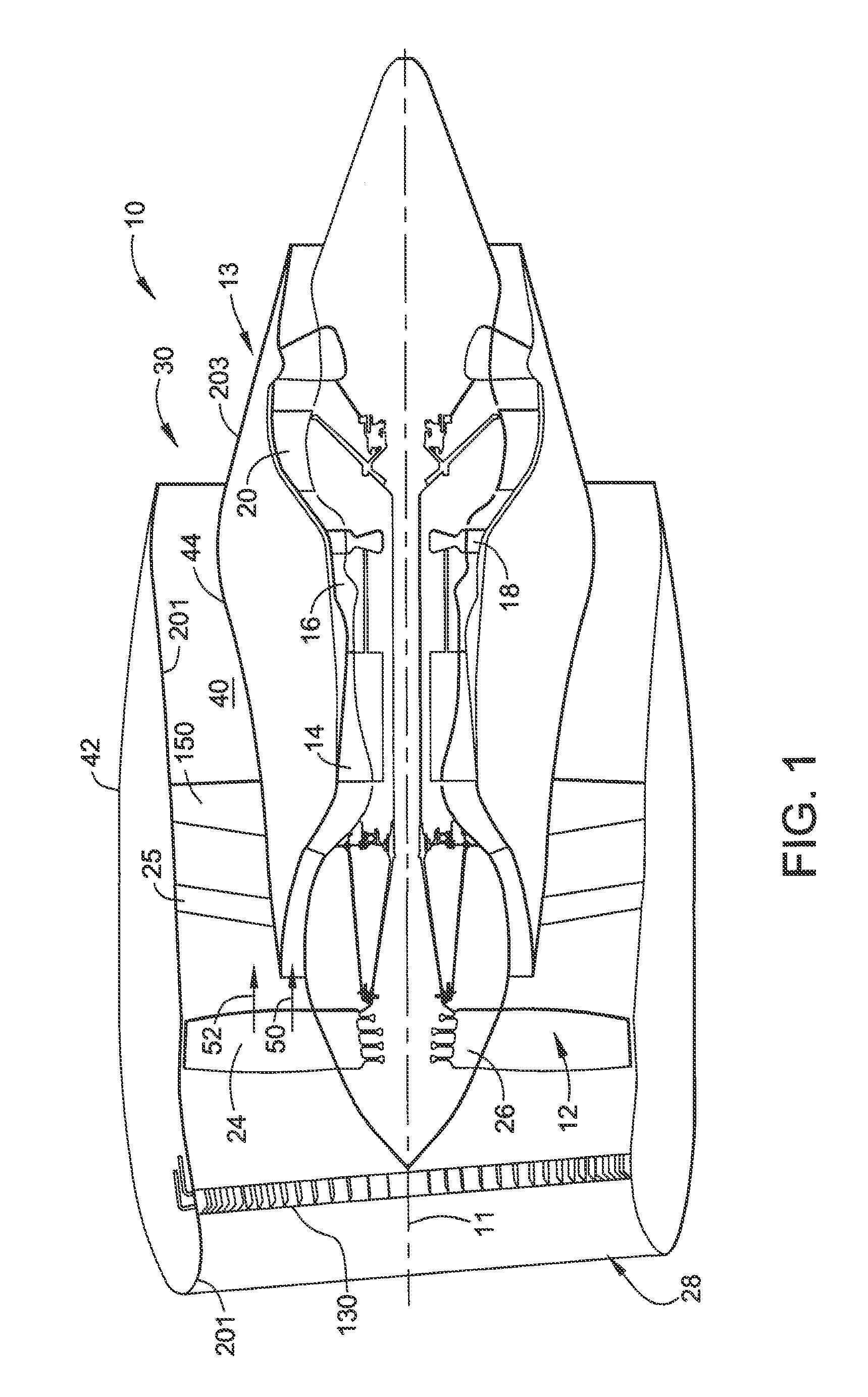
[0020]FIG. 1 is a schematic illustration of an exemplary gas turbine engine assembly 10 having a longitudinal axis 11. Gas turbine engine assembly 10 includes a fan assembly 12, and a core gas turbine engine 13. Core gas turbine engine includes a high pressure compressor 14, a combustor 16, and a high pressure turbine 18. In the exemplary embodiment, gas turbine engine assembly 10 may also include a low pressure turbine 20. Fan assembly 12 includes an array of fan blades 24 extending radially outward from a rotor disk 26. Engine 10 has an intake side 28 and an exhaust side 30. Gas turbine engine assembly 10 also includes a plurality of bearing assemblies (not shown in FIG. 1) that are utilized to provide rotational and axial support to fan assembly 12, compressor 14, high pressure turbine 18 and low pressure turbine 20, for example.

[0021]In operation, air flows through fan assembly 12 and is split by an airflow splitter 44 into a first portion 50 and a second portion 52. First porti...


PUM

PropertyMeasurementUnit
Temperatureaaaaaaaaaa
Flow rateaaaaaaaaaa

Abstract

A heat exchanger assembly for use in a gas turbine engine includes a bypass valve and at least one body portion. The body portion includes at least one de-congealing inlet channel in flow communication with the bypass valve, a plurality of cooling channels in flow communication with the bypass valve and the at least one de-congealing inlet channel, and at least one de-congealing outlet channel in flow communication with the bypass valve and the at least one de-congealing inlet channel. The bypass valve is configured to deliver a fluid between the at least one de-congealing inlet channel and the plurality of cooling channels during a first mode of operation to facilitate reducing a temperature of the fluid. The bypass valve is further configured to deliver the fluid between the at least one de-congealing inlet channel and the at least one de-congealing outlet channel during a second mode of operation.

Description

CROSS-REFERENCE TO RELATED APPLICATIONS[0001]This application is a non-provisional application and claims priority to U.S. Provisional Patent Application Ser. No. 61 / 680,323 filed Aug. 7, 2012 for “METHODS AND ASSEMBLY FOR OPERATING GAS TURBINE HEAT EXCHANGERS”, which is hereby incorporated by reference in its entirety.BACKGROUND OF THE INVENTION[0002]The application described herein relates generally to gas turbine engines, and more specifically to methods and apparatus for operating gas turbine engines.[0003]Gas turbine engines typically include an inlet, a fan, low and high pressure compressors, a combustor, and at least one turbine. The compressors compress air which is channeled to the combustor where it is mixed with fuel. The mixture is then ignited for generating hot combustion gases. The combustion gases are channeled to the turbine(s) which extracts energy from the combustion gases for powering the compressor(s), as well as producing useful work to propel an aircraft in fl...

Claims


Application Information

Patent Timeline
IPC IPC(8): F01D25/12F28F27/02
CPCF28F27/02F01D25/12F02C7/14F28F3/12F28F17/00F28D1/0471F28F1/022F28D2021/0026F28F2250/06Y10T29/49234Y02T50/60
Inventor STORAGE, MICHAEL RALPHMCQUEEN, DENNIS ALANFOSTER, ROGER EARL
Owner UNISON INDUSTRIES
Why Eureka
Try Eureka