Apparatus and Methods for Locating Source of and Analyzing Electromagnetic Radiation

a technology of electromagnetic radiation and antenna, which is applied in the direction of optical radiation measurement, radiation control devices, instruments, etc., can solve the problems of flight crew distraction, laser distraction of pilots, eye damage to flight crew,

Active Publication Date: 2014-02-20
NANOHMICS
View PDF3 Cites 18 Cited by
  • Summary
  • Abstract
  • Description
  • Claims
  • Application Information

AI Technical Summary

Benefits of technology

[0011]In embodiments of the invention, radiation is directed to a photodetector by positive lenses and flat mirrors. More particularly, positive lenses gather radiation, which may be from a laser or other source of radiation, and direct the radiation to a photodetector or to a mirror, from which it is reflected to a photodetector. The apparatus optionally includes means for wavelength, radiation intensity or “irradiance”, and temporal analysis. In optional embodiments, gathered radiation may be directed onto a color filter mosaic, comprising an optical filter or an array of optical filters, and thence onto a photodetector or photodetector array. The direction from which the radiation originates is determined from the size and location of the position or positions on the photodetector or photodetector array where the radiation is detected. The wavelength or wavelengths of the radiation are determined by identifying the amount of light passing through a specific f

Problems solved by technology

These often turn out to be the actions of pranksters, but the result may be distractions to the flight crew and, with sufficient power in the laser, eye damage to the flight crew.
Incidents of laser distraction of pilots usually occur when the aircraft is upon approach to land, which is the most dangerous part of flight.
In other cases, laser irradiation may be used to interfere with an optical communication system by either overloading optical detectors or by overpowering a legitimate signal with one containing interfering information.
Current laser detectors are inefficient and inaccurate at detecting the location of interfering radiation source, necessitating a need for the use of multiple, expensive detectors.
Furthermore, existing laser detection systems do not have the ability to determine whether a laser irradiating a craft is a danger requiring protective action or merely a nuisance to be ignored.
However, the

Method used


Image

  • Apparatus and Methods for Locating Source of and Analyzing Electromagnetic Radiation
  • Apparatus and Methods for Locating Source of and Analyzing Electromagnetic Radiation
  • Apparatus and Methods for Locating Source of and Analyzing Electromagnetic Radiation

Examples


example 1

Exemplary Radiation Detector, Data Processing Components, and Radiation Detection and Measurements

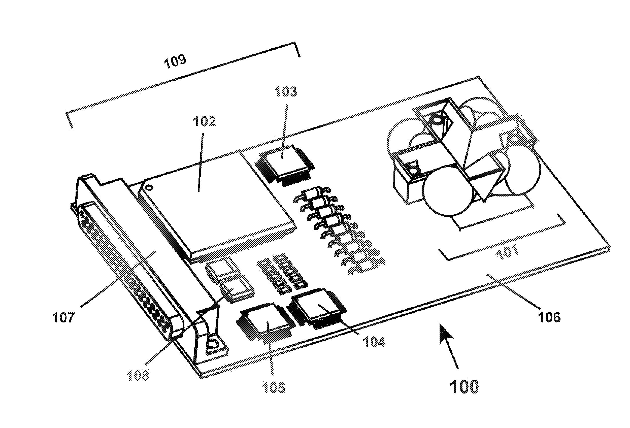
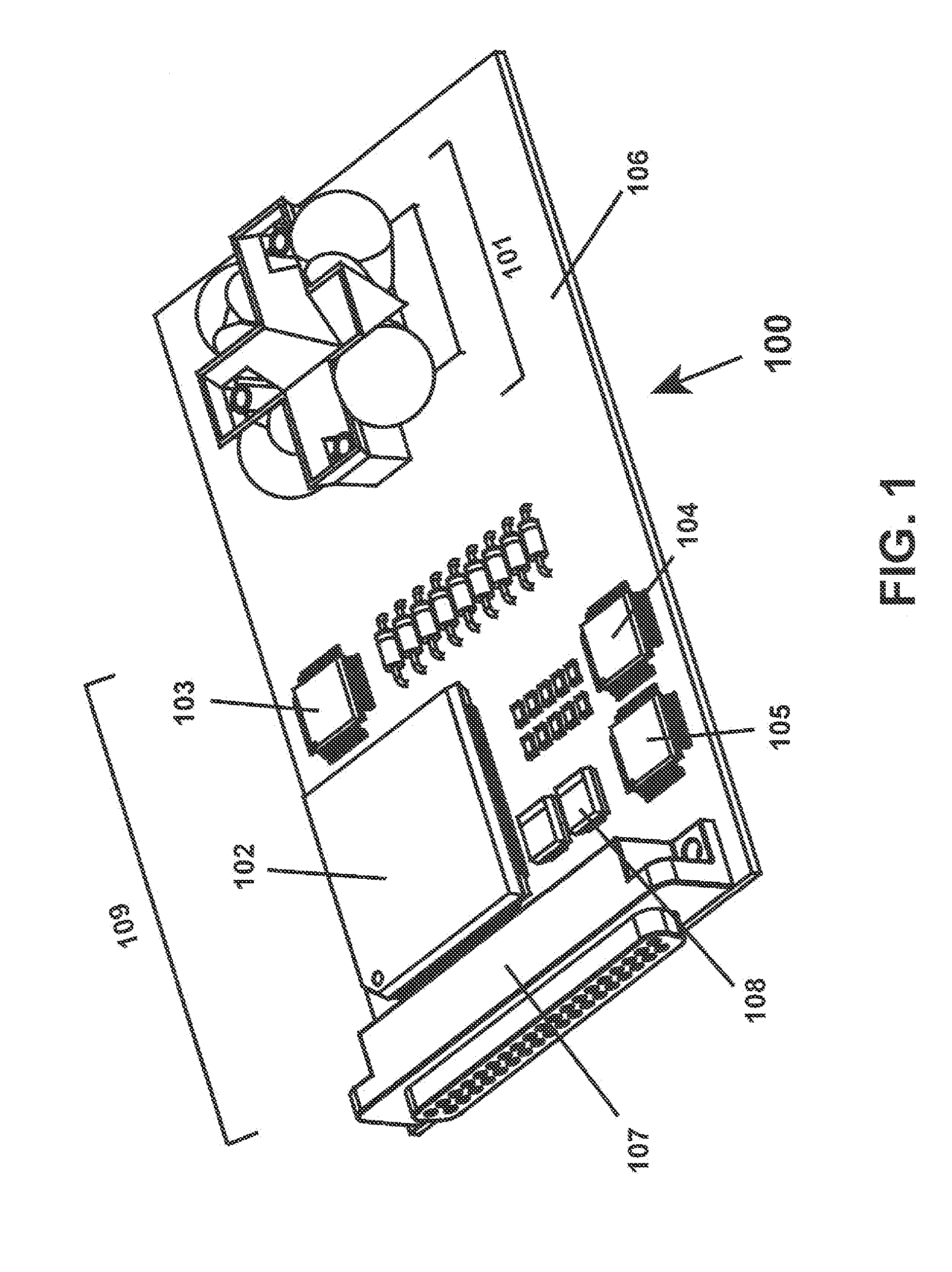
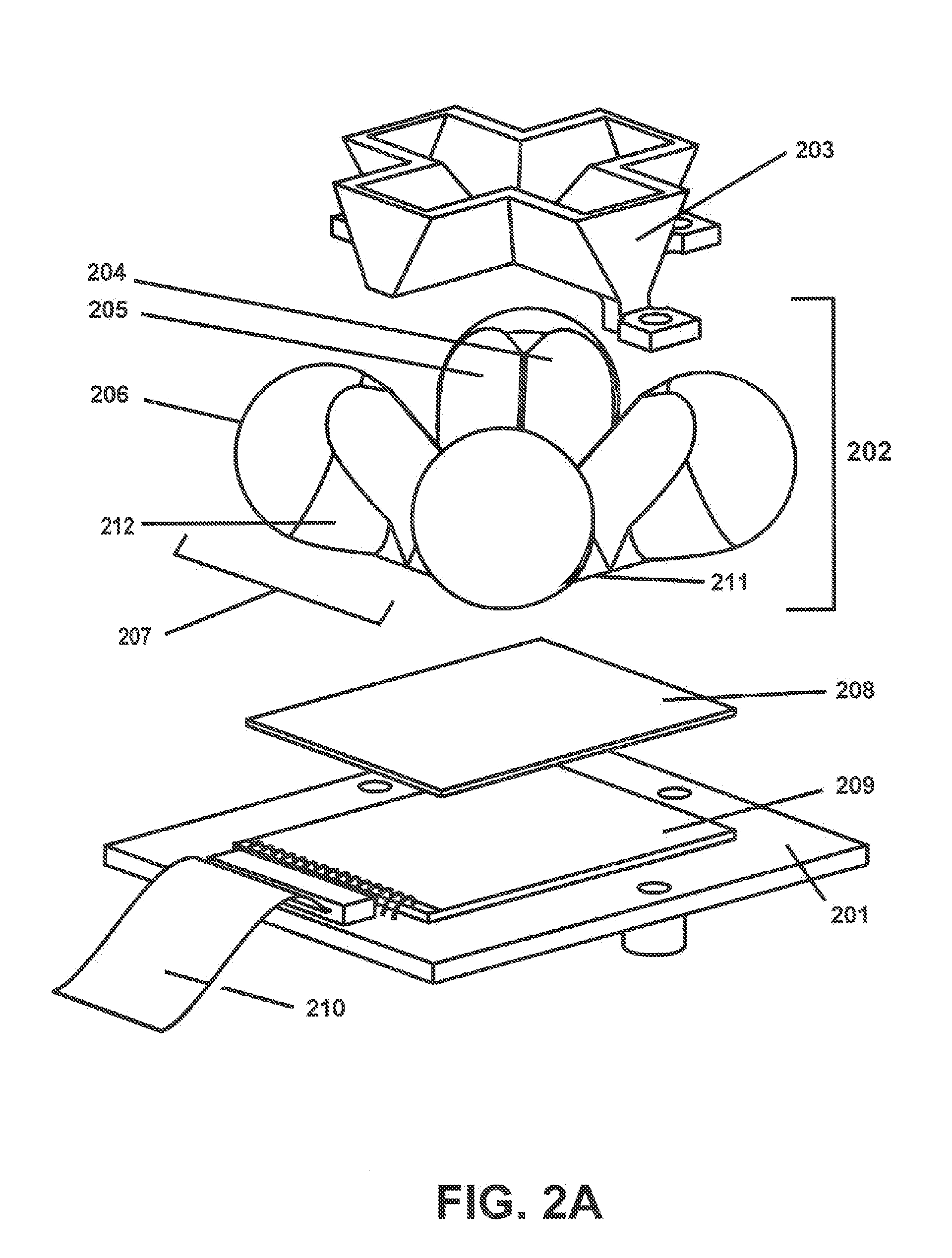
[0078]The inventors constructed an embodiment of radiation detector 101 and associated data processing components. The detector has a field of view far greater than one hemisphere (>2 sr). That is, it is able to detect radiation arriving from across a field of view comprising over an entire hemisphere, with an almost-constant collection aperture over the entire solid angle. The detector gathers radiation and computes angle-of arrival and wavelength with an accuracy of ±1° and ±20 nm, respectively, over the near-ultraviolet, visible, and near-infrared spectrum. The data processing components include a real-time signal processor that provides computational full-frame-rate threat detection and source geolocation processing. This technology was developed for use on low-earth-orbit satellites, to provide information on source location in the event of ground-based laser illumination of a spac...


PUM


Abstract

Detectors and methods for gathering, detecting and analyzing electromagnetic radiation are disclosed. A radiation detector includes one or more positive lenses to direct radiation to mirrors or to a photodetector. Coordinates of directed radiation are measured and interpreted to determine the angle of arrival. A color filter mosaic may be present to determine wavelengths of detected radiation. Temporal characteristics of the radiation may be measured.

Description

STATEMENT REGARDING FEDERALLY SPONSORED RESEARCH[0001]The invention was supported, in whole or in part, by United States Air Force Contract Number FA8650-06-C-1016. The Government has certain rights in the invention.BACKGROUND OF THE INVENTION[0002]1. Field of the Invention[0003]This invention relates to apparatus and methods for gathering electromagnetic radiation, measuring the direction to the source of the radiation, and analyzing the radiation. In some embodiments, optical components of the apparatus may be employed in solar power applications.[0004]2. Description of Related Art[0005]In recent years numerous instances of commercial aircraft being irradiated with laser beams have been reported. These often turn out to be the actions of pranksters, but the result may be distractions to the flight crew and, with sufficient power in the laser, eye damage to the flight crew. Incidents of laser distraction of pilots usually occur when the aircraft is upon approach to land, which is t...

Claims


Application Information

Patent Timeline
IPC IPC(8): H01L31/0232H01L27/14G01J1/04G01B11/26H01L27/146
CPCG01J1/0422G01S3/00G01J2003/2813G01J2001/4266G01J1/0411H01L27/14625H01L31/02327G01S3/784H01L27/14621G01J1/4257H01L27/146H01L31/0232G01J1/04H01L27/14G01J1/0492
Inventor ZOLLARS, BRYON G.SAVOY, STEVE M.MAYO, MICHAEL W.MITCHELL, DANIEL R.
Owner NANOHMICS
Why Eureka
Try Eureka