Surface Cleaning Apparatus

a surface cleaning and apparatus technology, applied in the direction of cleaning equipment, cleaning filter means, cleaning filters, etc., can solve the problems of reducing the amount of suction produced by suction motors, and reducing the cleaning efficiency of vacuum cleaners, so as to improve the cleaning performance of surface cleaning apparatuses, reduce the velocity of air flow, and improve the effect of performan

Active Publication Date: 2014-02-27
OMACHRON INTPROP
View PDF9 Cites 27 Cited by
  • Summary
  • Abstract
  • Description
  • Claims
  • Application Information

AI Technical Summary

Benefits of technology

[0007]It has been surprising determined that a vacuum cleaner which has an absence of a typical vortex finder may have improved performance despite the absence of the vortex finder, particularly in low air flow vacuum cleaners. It has been determined that a vortex finder produces back pressure. This back pressure provides a resistance to flow through the vacuum cleaner and, no other changes being made, reduces the velocity of the air flow at the dirty air inlet. At the same time, the absence of the vortex finder does not materially affect the efficiency of the cyclone chamber. Therefore, the cleaning performance of the surface cleaning apparatus may be improved.
[0008]According to another broad aspect of this disclosure, a vacuum cleaner, or other surface cleaning apparatus, is provided wherein a cyclone chamber is provided with a vortex finder that extends into the cyclone chamber less than the height of the cyclone air inlet. It has also been surprisingly determined that even by reducing the size of, (without making any other change) the cleaning performance of the surface cleaning apparatus may be improved.

Problems solved by technology

However, smaller motors typically produce less suction.
If the size of the dirty air inlet is maintained constant and no other changes are made to the air flow path through the vacuum cleaner, then reducing the amount of suction produced by a suction motor will reduce the cleaning efficiency of a vacuum cleaner.
While a battery pack having a large power capacity may be provided so as to provide a high level of current for an extended period of time, the weight of the battery pack may be excessive for use in a vacuum cleaner.
However, if the weight of the battery pack is reduced, then the operating life between charges may be low or the air flow produced by the surface cleaning apparatus may result in poor cleaning performance.

Method used


Image

  • Surface Cleaning Apparatus
  • Surface Cleaning Apparatus
  • Surface Cleaning Apparatus

Examples


Embodiment Construction

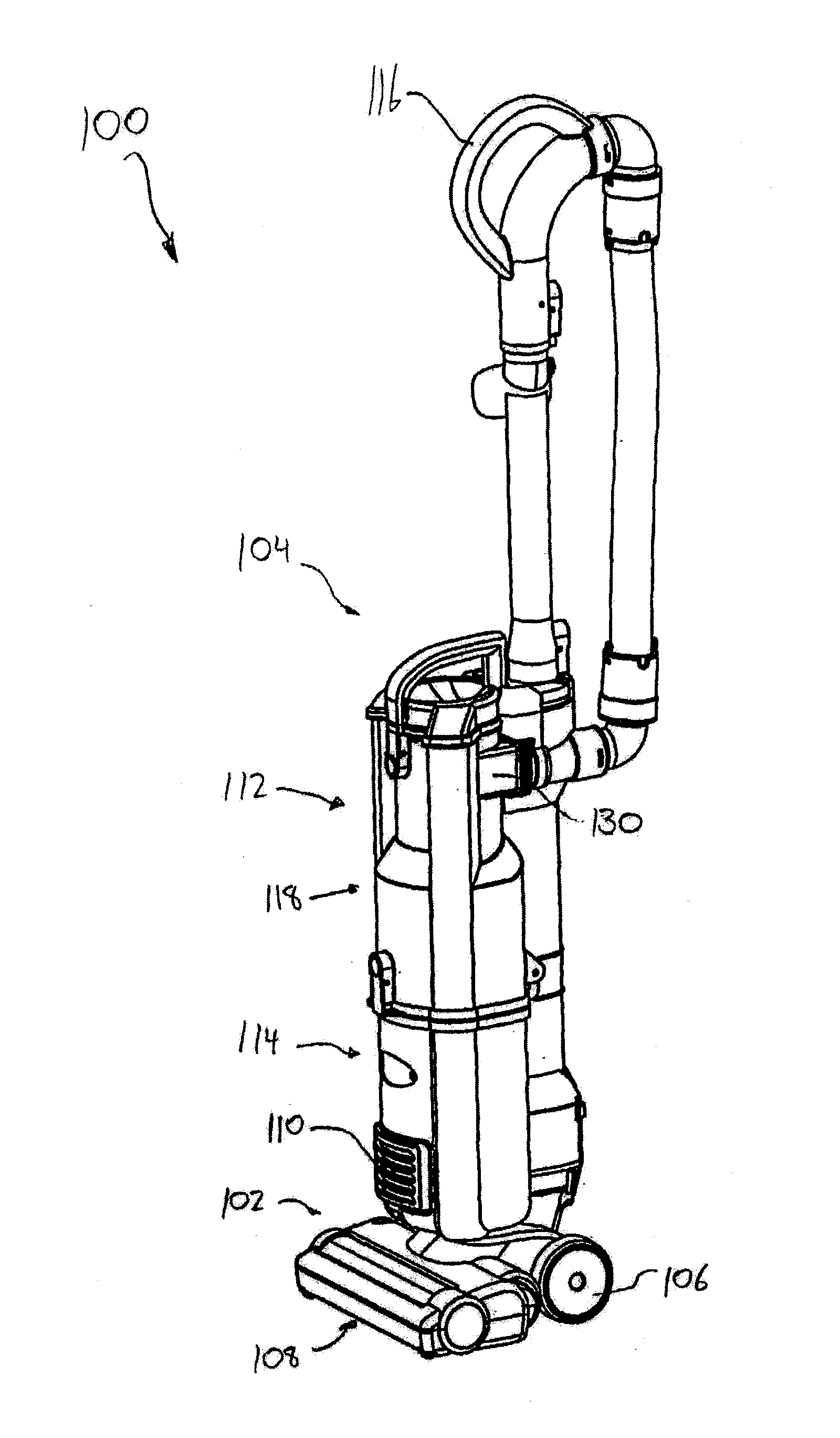
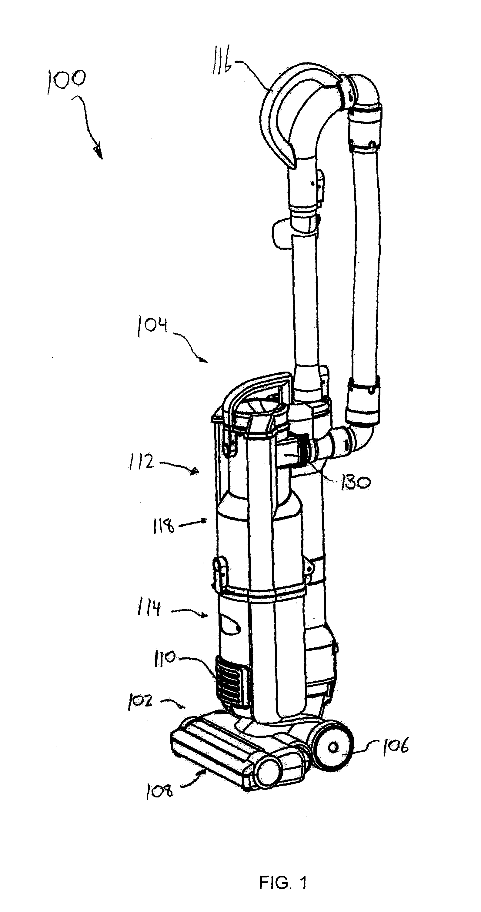
[0055]Referring to FIG. 1, an embodiment of a surface cleaning apparatus 100 is shown. In the embodiment illustrated, the surface cleaning apparatus 100 is a full size upright vacuum cleaner. In alternate embodiments, the surface cleaning apparatus may be another suitable type of surface cleaning apparatus, including, for example, a hand vacuum cleaner, a canister vacuum cleaner, a stick vac, a wet-dry vacuum cleaner and a carpet extractor.

[0056]The surface cleaning apparatus 100 may comprise an electrical cord to connect to an external power source, including, for example, a standard electrical outlet. Alternatively, or in addition to being connectable to an external power source, the surface cleaning apparatus 100 may comprise an onboard power source, including, for example one or more batteries. Optionally, the on board battery may be rechargeable, preferably while mounted to the surface cleaning apparatus 100.

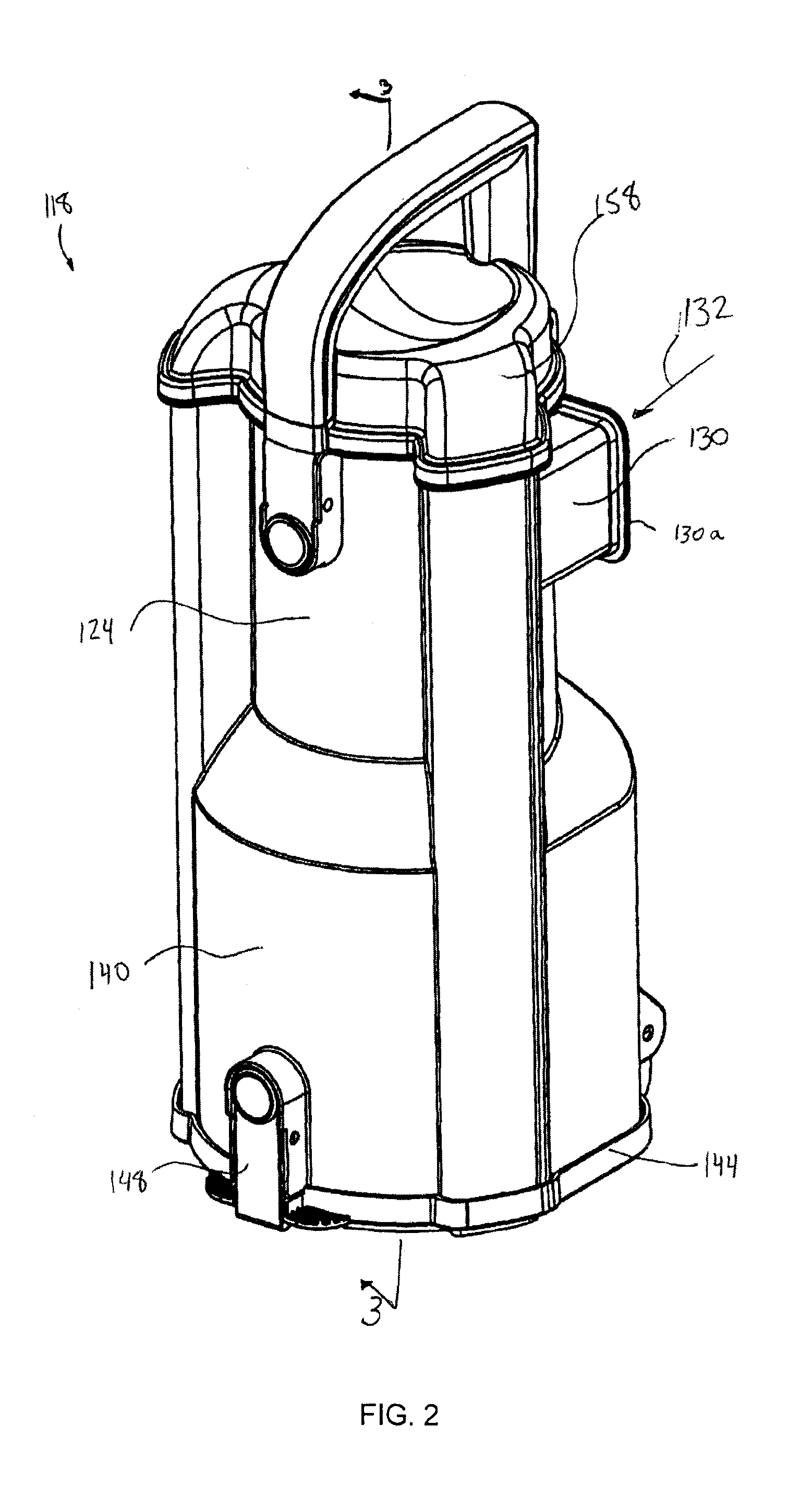
[0057]As exemplified in FIG. 1, the surface cleaning apparatus 100 inc...


PUM


Abstract

A surface cleaning apparatus comprises an air flow path extending from a dirty air inlet to a clean air outlet and includes a suction motor. The surface cleaning apparatus may be battery powered and/or may have a power requirement of 200 Watts or less. A cyclone chamber is provided in the air flow path and has an air outlet which is covered by a screen. In one embodiment, there is an absence of a vortex finder. In another embodiment, a vortex finder that extends into the cyclone chamber less than the height of the cyclone inlet and optionally less than the height of the cyclone inlet may be provided.

Description

FIELD[0001]The disclosure relates to surface cleaning apparatuses, such as vacuum cleaners having a suction motor that may produce a reduced air flow, such as a battery operated vacuum cleaner.INTRODUCTION[0002]Various constructions for surface cleaning apparatuses, such as vacuum cleaners, are known. Currently, many surface cleaning apparatuses are constructed using at least one cyclonic cleaning stage. Air is drawn into the vacuum cleaners through a dirty air inlet and conveyed to a cyclone inlet. The rotation of the air in the cyclone results in some of the particulate matter in the airflow stream being disentrained from the airflow stream. This material is then collected in a dirt bin collection chamber, which may be at the bottom of the cyclone or in a direct collection chamber exterior to the cyclone chamber (see for example WO2009 / 026709 and U.S. Pat. No. 5,078,761). One or more additional cyclonic cleaning stages and / or filters may be positioned downstream from the cyclone. ...

Claims


Application Information

Patent Timeline
Patent Type & Authority Applications(United States)
IPC IPC(8): A47L7/00
CPCA47L7/0038A47L5/24A47L5/32A47L9/1608A47L9/1666A47L9/1683A47L9/1691A47L5/362A47L7/0023
Inventor CONRAD, WAYNE ERNEST
Owner OMACHRON INTPROP
Why Eureka
Try Eureka