High-powered optical module safety systems and methods

a technology of optical modules and safety systems, applied in the field of fiber optic systems and methods, can solve the problems of large fraction of light to exit the fiber, damage to the fiber cable itself or equipment, fire hazards, etc., and achieve the effect of reducing the optical power output of the optical module and reducing the power of the optical pump

Active Publication Date: 2014-02-27
CIENA
View PDF6 Cites 16 Cited by
  • Summary
  • Abstract
  • Description
  • Claims
  • Application Information

AI Technical Summary

Benefits of technology

[0003]In an exemplary embodiment, a method includes provisioning an optical module; determining a baseline for a backscatter signal into the optical module based on the provisioning; continuously monitoring the backscatter signal in the optical module during operation of the optical module to detect variances in power of the backscatter signal; and, upon detecting a decrease in the power of the backscatter signal below a threshold, performing remedial actions associated with the optical module, wherein the threshold is set indicative of a fiber discontinuity at or near a port of the optical module. The threshold can be set based on the backscatter signal being attenuated twice by the fiber discontinuity in that the fiber discontinuity first attenuates an output signal from the optical module and second attenuates the backscatter signal associated with the output signal. The method can further include outputting a signal from the optical module to a fiber; tapping a small portion of power from the signal prior to the signal exiting the optical module; and detecting the backscatter signal from the small portion of power, wherein the backscatter signal is a signal produced by Rayleigh backscattering (RBS) of the signal in the fiber. The method can further include provisioning the optical module ensuring losses and back reflections of the signal into a fiber from the optical module are at acceptable levels; and determining the baseline for the backscatter signal based on the acceptable levels, wherein the backscatter signal is a signal produced by Rayleigh backscattering (RBS) of the signal in the fiber.
[0004]The method can further include performing an optical time domain reflectometer (OTDR) function on the fiber to ensure the acceptable levels, wherein the OTDR function is performed by the optical module. The backscatter signal can be continuously monitored at wavelengths of interest based on a high powered output signal from the optical module. The method can further include performing the remedial actions including at least one of raising an alarm, reducing optical power output of the optical module, reducing optical pump power in the optical module, and shutting off optical pumps in the optical module. The method can further include, upon detecting an open connection through monitoring the backscatter signal, turning off at least one optical component in the optical module. The method can further include continuously monitoring a signal associated with an optical component internal to the optical module; and, upon detecting a change in a ratio of power of the backscatter signal to the signal, performing remedial actions associated with the optical module.
[0005]In another exemplary embodiment, an optical module includes at least one optical device within the optical module associated with a high powered optical signal; a line port from which the high powered optical signal exits the optical module into a fiber span; a photodetector coupled to the line port and configured to measure optical power of a backscatter signal from the fiber span associated with high powered optical signal; and circuitry communicatively coupled to the photodetector and the at least one optical device, the circuitry configured to detect a decrease in the power of the backscatter signal below a threshold and perform a remedial action on the at least one optical device based thereon, wherein the threshold is set indicative of a fiber discontinuity at or near the line port. The threshold can be set based on the backscatter signal being attenuated twice by the fiber discontinuity in that the fiber discontinuity first attenuates an output signal from the optical module and second attenuates the backscatter signal associated with the output signal. The optical module can further include an optical power tap tapping a small portion of optical power from the line port to the photodetector, wherein the circuitry detects the backscatter signal from the photodetector the small portion of optical power, wherein the backscatter signal is a signal produced by Rayleigh backscattering (RBS) of the signal in the fiber.
[0006]The circuitry can be set with the threshold subsequent to performing fiber tests on the span fiber and ensuring losses and back reflections of the high powered optical signal into the span fiber are at acceptable levels. The optical module can further include an optical time domain reflectometer (OTDR) function configured to determine if the span fiber is at the acceptable levels. The optical module can further include a second photodetector coupled to the least one optical device and the circuitry and configured to measure optical power of an internal signal from the least one optical device; wherein the circuitry is configured to detect a change in a ratio of power of the backscatter signal to the internal signal and perform the remedial action based thereon.
[0007]In yet another exemplary embodiment, an optical amplifier includes at least one optical pump within the optical amplifier associated with or amplifying a high powered optical signal; a line port from which the high powered optical signal exits the optical amplifier into a fiber span; a photodetector coupled to the line port and configured to measure optical power of a backscatter signal from the fiber span associated with high powered optical signal; and circuitry communicatively coupled to the photodetector and the at least one optical device, the circuitry configured to detect a fiber discontinuity based on monitoring the backscatter signal and perform a remedial action on the at least one optical pump based thereon. Optionally, the optical amplifier is in a Raman amplifier configuration; the circuitry is configured to detect a change in the backscatter signal below a threshold; the threshold is set indicative of a fiber discontinuity at or near the line port; and the threshold is set based on the backscatter signal being attenuated twice by the fiber discontinuity in that the fiber discontinuity first attenuates an output signal from the optical module and second attenuates the backscatter signal associated with the output signal. The at least one optical pump can include at least one Raman pump, and wherein the backscatter signal can be a signal produced by Rayleigh backscattering (RBS) of the signal in the fiber at wavelengths of the at least one Raman pump. The optical amplifier can further include components integrated within the optical amplifier to perform an optical time domain reflectometer (OTDR) function; wherein the OTDR function is utilized to ensure acceptable conditions on the fiber span, and once the acceptable conditions on the fiber span are determined, a baseline is established for the backscatter signal with the remedial action being performed if the backscatter signal is at a power level of the baseline minus the threshold. Alternatively, the optical amplifier includes an erbium doped fiber amplifier (EDFA), wherein the at least one optical pump is coupled to a spool of erbium doped fiber in the optical amplifier, and the optical amplifier further includes a second photodetector coupled to an output of the erbium doped fiber and configured to measure optical power of a signal from the erbium doped fiber; wherein the circuitry is configured to detect a change in a ratio of power of the backscatter signal to the signal and perform the remedial action based thereon.

Problems solved by technology

Another potential safety issue with high-power optical amplifiers is a case where there is an inadvertent fiber pinch in fiber carrying high power light from the high-power amplifiers.
A tight bend can cause a large fraction of the light to exit the fiber and to damage the fiber cable itself or equipment that comes in contact with it, or worse to injure a user, for example by burning the fingers that are pinching the fiber.
Even worse, this could lead to a fire hazard.
Disadvantageously, conventional shutdown / detection mechanisms which rely either on interruption of an OSC signal or high pump back reflection will not detect a fiber pinch.
Additionally, as interconnection complexity increases with optical amplifier systems and methods, more and more opportunities exist for fiber pinches near the launch point of the pumps.

Method used


Image

  • High-powered optical module safety systems and methods
  • High-powered optical module safety systems and methods
  • High-powered optical module safety systems and methods

Examples


Embodiment Construction

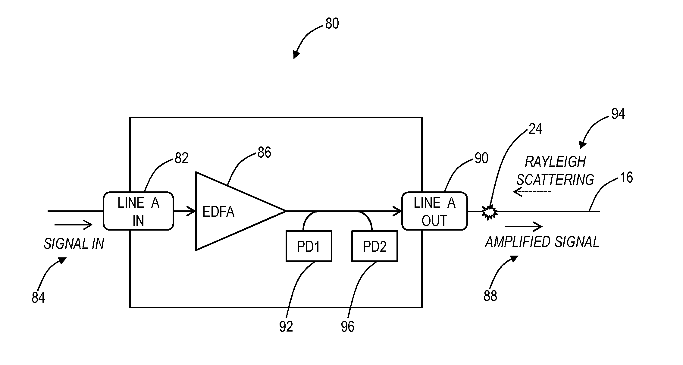
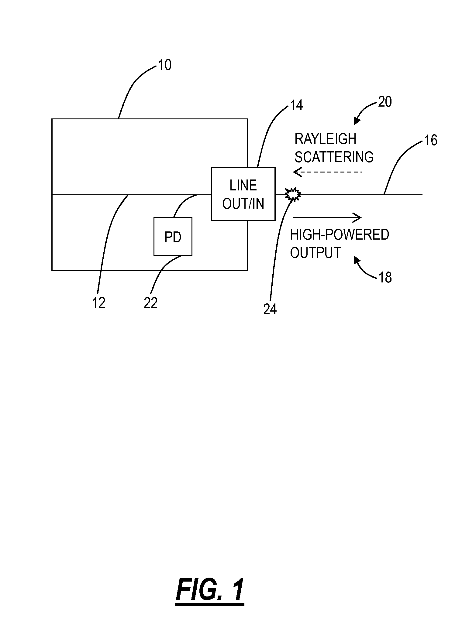
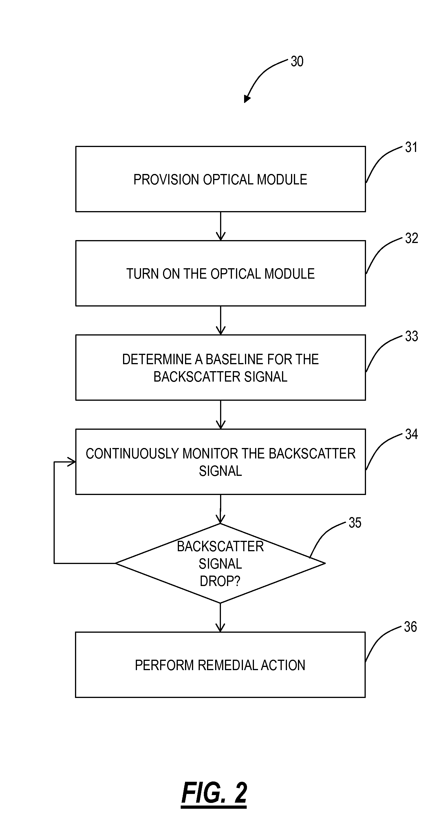
[0014]In various exemplary embodiments, high-powered optical module safety systems and methods are described which can detect discontinuities such as a fiber pinch and perform automatic remedial mechanisms based thereon. The high-powered optical module safety systems and methods provide an automatic mechanism to detect and quickly shutdown or reduce amplifier power before any significant damage can occur. The high-powered optical module safety systems and methods can apply to Raman amplifiers and / or EFDAs. Advantageously, the high-powered optical module safety systems and methods solve an important safety problem for users of high-power amplifiers in an efficient implementation that can reuse components typically are already in place in most Raman amplifiers and EDFAs, therefore adding little to no cost.

[0015]Variously, the high-powered optical module safety systems and methods monitor a backscattered signal to detect fiber pinches. Advantageously, the use of the backscattered signa...


PUM

PropertyMeasurementUnit
distanceaaaaaaaaaa
insertion lossesaaaaaaaaaa
poweraaaaaaaaaa

Abstract

A method, optical module, and optical amplifier are configured to detect fiber discontinuities at or near a port from which high powered optical signals are input into a fiber span. These fiber discontinuities can include fiber pinches, and are detected by monitoring for slight changes in a backscatter signal. Detection is quick and efficient based on the backscatter signal being attenuated by the fiber discontinuities twice, namely once as the high powered optical signals and again as the associated backscatter signal of the high powered optical signals returning to the port. Various remedial actions can be taken upon detecting fiber pinches at or near the port.

Description

FIELD OF THE INVENTION[0001]Generally, the field of art of the present disclosure pertains to fiber optic systems and methods, and more particularly, to high-powered optical module safety systems and methods which can detect discontinuities such as a fiber pinch and perform automatic, remedial mechanisms based thereon.BACKGROUND OF THE INVENTION[0002]Conventionally, optical amplifier systems and methods utilize automatic shutdown mechanisms to comply with relevant standards for laser eye safety. Exemplary optical amplifier systems and methods can include Raman amplifiers, Erbium Doped Fiber Amplifiers (EDFAs), and the like. These conventional systems and methods are designed to shut down pumps or the like in an optical amplifier in the event of a fiber cut or open connector. From a detection perspective, fiber cuts are detected by a loss of signal such as, for example, due to an interruption of an optical service channel (OSC). Open connections can be detected using a back reflectio...

Claims


Application Information

Patent Timeline
Patent Type & Authority Applications(United States)
IPC IPC(8): G01N21/49G01N21/55
CPCH01S3/06754H01S3/094003H01S3/1608H01S3/302H01S3/0014H01S3/1001G01M11/3145G01M11/335
Inventor ARCHAMBAULT, JEAN-LUCBAO, JUN
Owner CIENA
Why Eureka
Try Eureka