Recoil force mitigating device for firearms

a technology of shock absorption and shock absorption, which is applied in the field of shock absorption devices, can solve the problems of many ways in which devices, particularly electro-optic devices, can sustain damage, and the source of damage is recoil forces, so as to reduce the weight of electro-optic devices, reduce wear and tear, and save weight

Active Publication Date: 2014-03-06
CADEX
View PDF9 Cites 29 Cited by
  • Summary
  • Abstract
  • Description
  • Claims
  • Application Information

AI Technical Summary

Benefits of technology

[0005]Presented herein is a shock mitigating device for cooperating with a firearm in the form of a recoil rail assembly which mitigates the aforementioned recoil forces and protects firearm accessories and the firearm. The recoil forces are mitigated by the recoil rail assembly of the present invention which buffers and absorbs variable amounts of peak recoil forces, thereby reducing the forces transferred from the firearm firing, to any accessories, such as electro-optic devices. The recoil rail assembly as described herein contemplates use on all weapon types; from light, portable, infantry weapons to heavy infantry weapons, such as a .50 caliber machine gun. Even a fixedly mounted firearm would benefit from the present invention.
[0008]Novel recoil force mitigating means, according to one embodiment, are beneficial, for example, for long travel and include a central, longitudinally extending shaft and a pair of springs for absorbing recoil forces. This arrangement provides long, gradual curve to manage recoil forces and the spring rate may be altered to accommodate different firearm firing rates and enables the recoil reset rate to be matched with the weapon. A second recoil force mitigating means described herein is beneficial, for example, for a shorter travel. This embodiment includes at least one or more deformable, elastomeric members positioned in a predetermined location to mitigate recoil forces by deforming and absorbing the forces and provide protection to accessories mounted on the second rail. This embodiment utilizes a short moment curve to mitigate recoil forces. Another embodiment utilizes a combination of a spring or springs and an elastomeric member or members to mitigate recoil forces and minimize or prevent transference thereof to the second rail supporting the accessories.
[0010]While certain combinations of the various rail configurations, recoil force mitigating members, and mounting configurations are illustrated and described in detail below, it is to be understood that different permeations of these variables are within the scope of the present invention. That is, any of the various rail configurations may be used in combination with any one of the force mitigating means and any of these combinations may be mounted to the firearm utilizing any of the described mounting means. Additionally, the mitigating means can buffer or mitigate forces in both the aft and fore direction, or just one direction.
[0011]A shock mitigating device as described herein provides savings in life cycle costs such as in-service and a reduction of wear and tear on electro-optic devices' image intensifier tubes, optical lenses, battery housings and electronics. Moreover, the weight of the electro-optic device may be reduced because fewer recoil forces will be absorbed. Weight savings can also be achieved because less weight will be necessary to harden image intensifier tubes, optical lenses and electronics to manage shock. In addition to providing life cycle cost savings, the present invention also provides commonality of training and commonality of logistics. The shock mitigating device as described herein allows an electro-optic device to be used across greater variety of weapon systems, with different recoil characteristics. For example, the same electro-optic device may be used on different weapons such as a carbine and on a heavy machine gun. The recoil rail assembly, according to the present invention, enables weapon designers to create lighter weapon designs as less emphasis is needed on absorption of shock by devices mounted to the weapon platform. The recoil rail may be integrated with future powered rail systems whereby recoil rail designs will maintain circuit continuity between power sources and attached electro-optic / accessory devices. Additionally, the recoil rail assembly allows integration of items such as grenade launchers and shotguns to a parent weapon, with reduction of shock risk to electro-optic accessories. The recoil rail assembly also ensures there is little or no movement of the electro-optic accessory due to shock when the weapon or weapon sub-system is fired.
[0012]Cumulative effects of shock can also weaken retention springs in the battery housing, resulting in a failure of the power source. Firing forces can cause the battery to move within the battery housing causing loss of continuity and resulting in failures such as system shut down or reboot of electro-optic system. Electronic components can be affected by short and long term effects of weapon firing shock. Reticles and lenses can be shifted by cumulative effects of firing shock or by a significant impact event under field conditions. The result may be a loss of zero or a complete failure of the optical path. Forces acting on the electro-optic selector switches, controls and zeroing mechanisms may also be impacted by recoil forces. These risks are reduced and / or eliminated by the present invention.
[0013]Other benefits are achieved to the weapon itself in that the weapon itself absorbs less force when recoil forces are mitigated by a recoil rail assembly. For example, electro-optic devices mounted on heavy weapons on a vehicle or aircraft are subject to vibration during operation of the vehicle / aircraft. The recoil rail provides a degree of mitigation from the frequency of vibrations from forces in addition to recoil forces. Moreover, under field conditions, impact forces during use can be enough to damage accessory mounting brackets, or cause shifting of reticle or lens. Forces can shake batteries to cause system shut down, reboot of electro-optics, or cause an electro-optic system to shut down. An electro-optic device using a recoil rail assembly has increased chance to survive such an impact event. These and other benefits and advantages are provided by the shock mitigating device as described in more detail below.

Problems solved by technology

Such devices include costly and mechanically precise instruments including precision optics and electronics, hereinafter referred to as “electro-optic devices”.
Under firing conditions, devices, particularly electro-optic devices, can sustain damage in many ways.
One source of damage is from recoil forces (often called kickback or simply kick) which are the backward momentum of a gun when it is discharged.
Under firing conditions, electro-optics can be damaged in a number of ways.
Recoil forces can cause the body of a day scope to flex, resulting in shifting of optical lenses and reticles.
With regard to night vision, laser and white light devices, the precision circuitry of electro-optics can be damaged by the shock of firing forces.
Cumulative effects of shock can also weaken retention springs in the battery housing, resulting in a failure of the power source.
Firing forces can cause the battery to move within the battery housing causing loss of continuity and resulting in failures such as system shut down or reboot of electro-optic system.
Electronic components can be affected by short and long term effects of weapon firing shock.
The result may be a loss of zero or a complete failure of the optical path.
For example, electro-optic devices mounted on heavy weapons on a vehicle or aircraft are subject to vibration during operation of the vehicle / aircraft.
Moreover, under field conditions, impact forces during use can be enough to damage accessory mounting brackets, or cause shifting of reticle or lens.

Method used


Image

  • Recoil force mitigating device for firearms
  • Recoil force mitigating device for firearms
  • Recoil force mitigating device for firearms

Examples


first embodiment

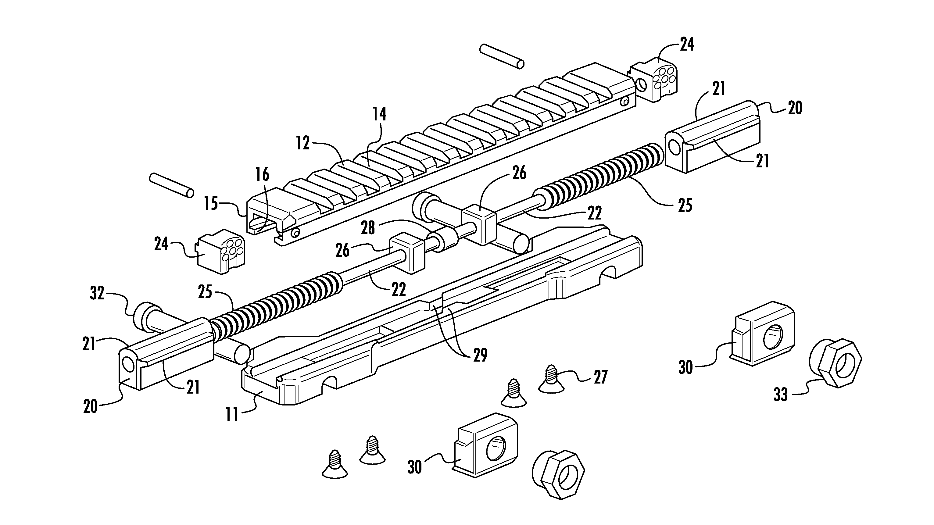
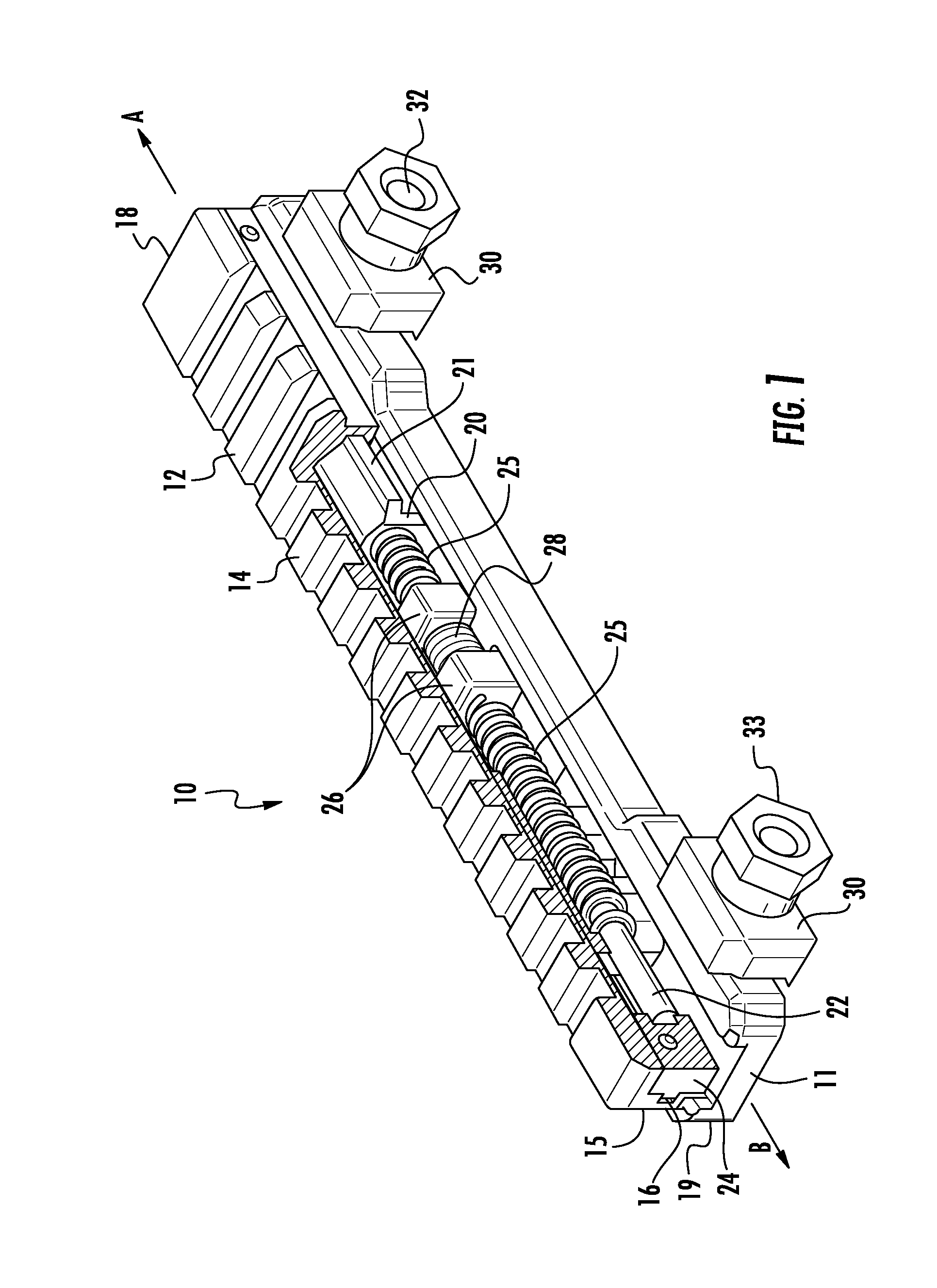
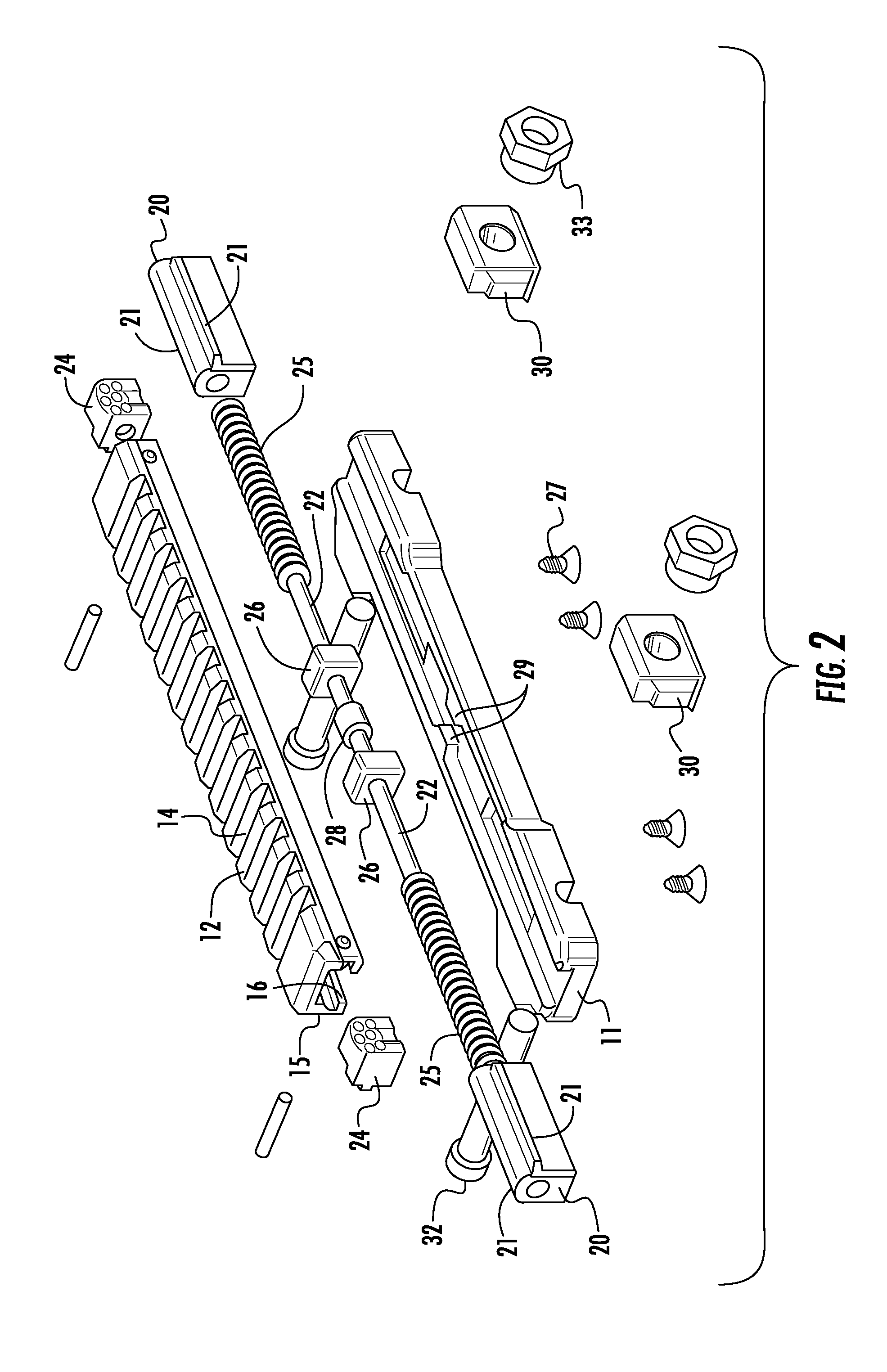
[0043]In a first embodiment, as illustrated in FIG. 1, the recoil rail assembly 10 includes a first, or base, rail 11 and a second rail 12 slideably mounted upon base rail 11. The second rail 12 is configured with an upper surface 14 for supporting accessories thereon, and side walls 15 each having an inwardly extending flange 16. The first rail 11 has a first, fore end 18 facing in the direction A of bullet discharge, and a second, aft end 19 facing in the direction B of the shooter. The base rail 11 is configured to receive a pair of blocks 20 which define at least one, and preferably a pair, of longitudinally and outwardly extending flanges 21 as shown in FIGS. 1 and 2. The flanges 16 of the second rail 12 are configured to mate with the block flanges 21 so as to secure the second rail 12 thereon in a slideable manner, and also to stabilize the second rail 12 and eliminate longitudinal rotation thereof. Accordingly, the first rail 11 and second rail 12 define a cavity there betwe...

second embodiment

[0047]A second embodiment is illustrated in FIGS. 4-6 wherein the recoil rail assembly 10 embodies a different recoil force mitigating means and is differently configured. More specifically, the second rail 12 is mounted on the central shaft 22 with the use of two end caps 35. The shaft 22 is received within two guides 36. The material used for the guide 36 and the shaft 22 are selected in the way to produce the lowest friction possible. At least one, and preferably at least two, cushion members 38 are provided and may be adjusted with a screw 39 in a way that they stabilize the rail 12 and substantially eliminate longitudinal rotation. In this design, the cushions 38 bias against the bottom of the rail 12 but they can be positioned in another way to be able, for example, to bias against the side walls 15 of the rail. A bushing 28 is fixed at the center of the shaft 22. When a shock occurs, the second rail 12 moves in the fore direction A relative to the shaft 22 of the first rail 1...

third embodiment

[0048]A third embodiment is illustrated in FIGS. 7-12. According to this embodiment, the first and second rail arrangement and the recoil force mitigating device are modified. Additionally, the recoil rail assembly 10 includes a first or base rail 53, a second, slideable rail 12, and an intermediate rail 42. In contrast to previously described embodiments, there is not a central shaft. FIG. 9 provides an exploded view of the rail assembly. The second rail 12 is attached to the intermediate rail 42 with two screws 43 which cooperate with a respective T-nut or mating member 49. The intermediate rail 42 defines at least one, and preferably a pair of apertures 41 through which screws 43 extend. As apparent in FIG. 9, the aperture 41 is of sufficient dimensions to provide clearance for the screw 43 to move longitudinally to enable the second rail 12 to move relative to the intermediate rail 42. The T mating member 49 cooperates with the screw 43 to secure the second rail 12 to the recoil...


PUM


Abstract

A recoil force mitigating device for cooperating with a firearm to mitigate recoil forces imparting undesirable forces to mounted firearm accessories. The recoil force mitigating device includes a recoil rail assembly having a first rail for mounting to the firearm and a slideable second rail for mounting accessories. A recoil force mitigating means is positioned between the first and second rails to mitigate transfer of forces, such as recoil forces, from the first rail to the second rail.

Description

CONTINUITY DATA[0001]This application claims priority to and the benefit of U.S. Provisional Patent Application No. 61 / 540,514, filed on Sep. 28, 2011, which is incorporated herein in its entirety.FIELD OF THE INVENTION[0002]This invention relates generally to firearms, and more particularly to a shock mitigating device for cooperating with the firearm to mitigate recoil forces imparting undesirable forces to, for example, mounted firearm accessories.BACKGROUND OF THE INVENTION[0003]Modern firearms, including those employed in military and law enforcement applications, often include various accessories to assist the shooter. Such devices include costly and mechanically precise instruments including precision optics and electronics, hereinafter referred to as “electro-optic devices”. Electro-optic devices may be mounted directly to the firearm or indirectly on a mount associated with the firearm. Conventional mounting means include securing accessories to the firearm with a Picatinny...

Claims


Application Information

Patent Timeline
Patent Type & Authority Applications(United States)
IPC IPC(8): F41A25/10
CPCF41A25/10F41G11/002F41G11/003
Inventor DEXTRAZE, SERGELOPEZ, ERICH
Owner CADEX
Why Eureka
Try Eureka