Imaging member for offset printing applications

a technology of offset printing and imaging plates, applied in the field of imaging members, can solve the problems of not being able to accommodate true high-speed variable data printing, not being able to create and print new patterns from one page to the next, and the cost of permanently patterned imaging plates or cylinders is amortized over the number of copies

Active Publication Date: 2014-03-06
XEROX CORP
View PDF3 Cites 28 Cited by
  • Summary
  • Abstract
  • Description
  • Claims
  • Application Information

AI Technical Summary

Benefits of technology

[0004]The ink may be transferred directly to a target substrate, such as paper, or may be applied to an intermediate surface, such as an offset (or blanket) cylinder in an offset printing system. The offset cylinder is covered with a conformable coating or sleeve with a surface that can conform to the texture of the target substrate, which may have surface peak-to-valley depth somewhat greater than the surface peak-

Problems solved by technology

However, they do not permit creating and printing a new pattern from one page to the next without removing and replacing the print cylinder and/or the imaging plate (i.e., the technique cannot accommodate true high speed variable data pri

Method used


Image

  • Imaging member for offset printing applications
  • Imaging member for offset printing applications
  • Imaging member for offset printing applications

Examples


example 1

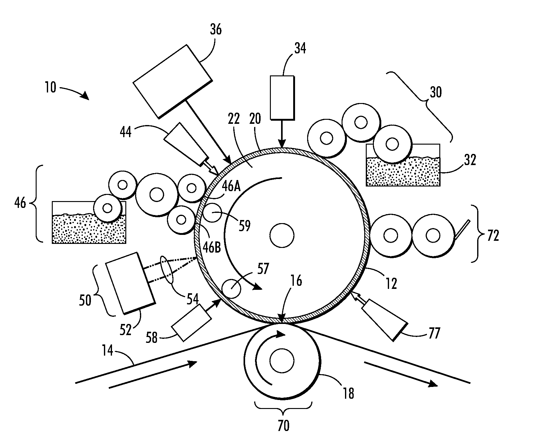
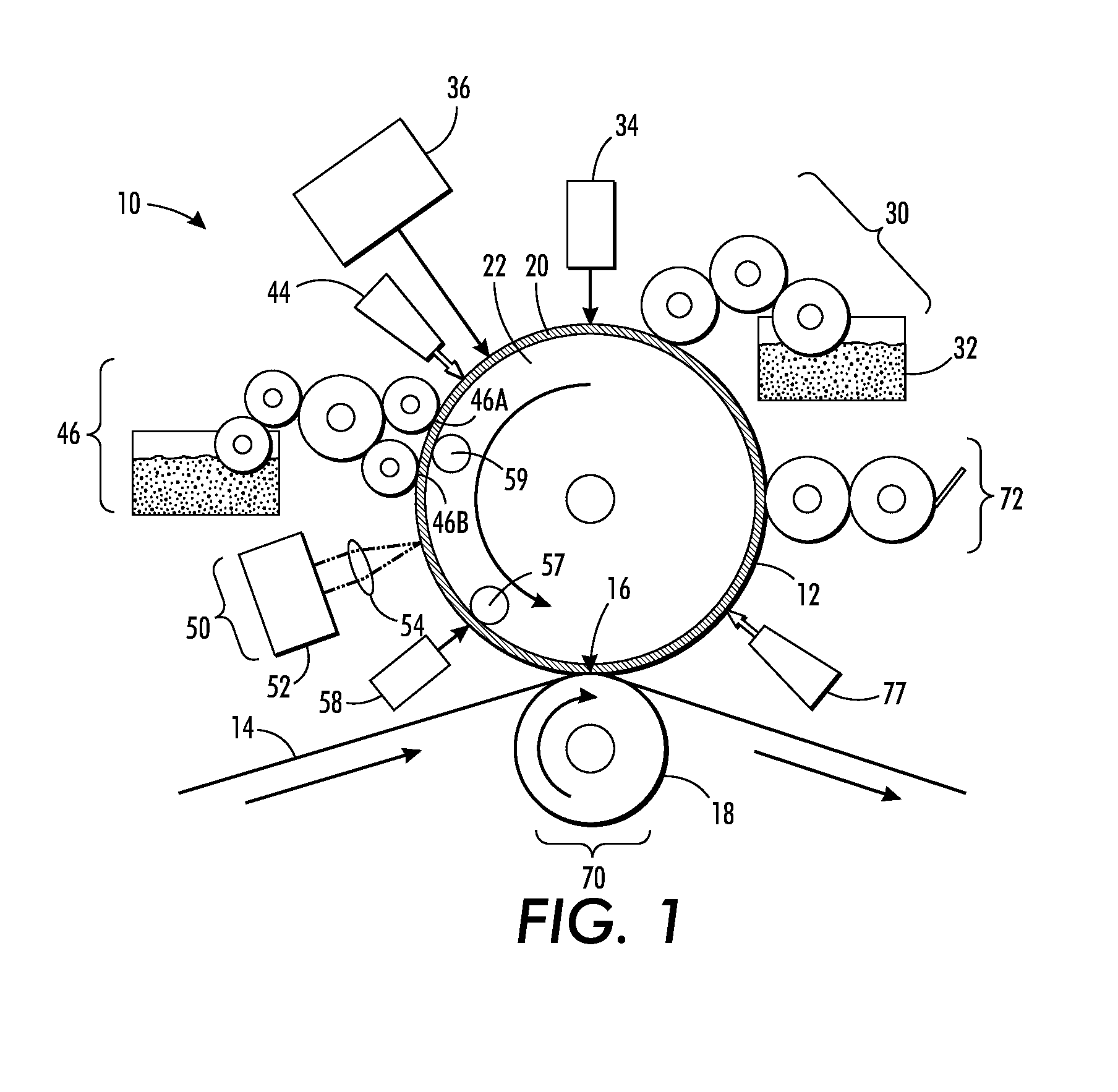
[0085]CF1-3510 (commercially available from Nusil), a two component, pourable fluorosilicone elastomer that is thermally curable, was loaded into a ball milling jar with black iron oxide particles, a solvent, and a ball milling media. The material was tumble milled for a period of from 14 to 16 hours. The milled material was removed and a catalyst was added. The material contained 10 wt % of iron oxide (FeO). The composition comprising the fluorosilicone and iron oxide particles was deposited on a textured, parylene coated mold (Agfa) to form the imaging member plate. The imaging member plate had a smooth side and a rough side (i.e. microtextured). The plate was then thermally cured at 150° C. for one hour. The filler-loaded, crosslinked composition was removed from the mold.

[0086]As a Comparative Example, a corresponding plate was made using a silicone available from Toray. This plate contained 10 wt % of carbon black (CB). The Toray silicone was a dimethyl-substituted silicone, an...


PUM


Abstract

An imaging member includes a surface layer comprising a fluorosilicone and an infrared-absorbing filler. At least 75% of the siloxane units in the fluorosilicone are fluorinated. Methods of manufacturing the imaging member and processes for variably lithographic printing using the imaging member are also disclosed.

Description

RELATED APPLICATIONS[0001]The disclosure is related to U.S. patent application Ser. No. 13 / 095,714, filed on Apr. 27, 2011, titled “Variable Data Lithography System,” the disclosure of which is incorporated herein by reference in its entirety. The disclosure is related to co-pending U.S. patent application (Attorney Docket No. 056-0513), filed on the same day as the present disclosure, titled “Imaging Member for Offset Printing Applications,” the disclosure of which is incorporated herein by reference in its entirety; co-pending U.S. patent application (Attorney Docket No. 056-0512), filed on the same day as the present disclosure, titled “Imaging Member for Offset Printing Applications,” the disclosure of which is incorporated herein by reference in its entirety; co-pending U.S. patent application (Attorney Docket No. 056-0511), filed on the same day as the present disclosure, titled “Imaging Member for Offset Printing Applications,” the disclosure of which is incorporated herein b...

Claims


Application Information

Patent Timeline
IPC IPC(8): B41F1/18B28B7/36B41F1/16G02B5/22
CPCB41F1/16B41F1/18B41F7/00B41M1/06B41M5/025B41M5/03B41N10/00G02B5/208G02B5/22G03G7/0013G03G7/0046G03G15/101G03G15/751
Inventor KANUNGO, MANDAKINIORNATSKA, MARYNAGERVASI, DAVID J.HOWE, PATRICK J.BADESHA, SANTOKH S.LESTRANGE, JACKKELLY, MATTHEW M.
Owner XEROX CORP
Why Eureka
Try Eureka