Movable pixelated filter array

a filter array and pixelated technology, applied in the field of pixelated filter arrays, can solve the problems of undesirable fixed-in-place pixelated filter arrays (color filters and/or polarization filters), and reducing signal strength and therefore range, so as to reduce system transmittance, reduce signal strength, and high signal strength

Active Publication Date: 2014-03-06
RAYTHEON CO
View PDF5 Cites 32 Cited by
  • Summary
  • Abstract
  • Description
  • Claims
  • Application Information

AI Technical Summary

Benefits of technology

[0003]Fixed-in-place pixelated filter arrays (of color filters and / or polarization filters) are undesirable for use in sensitive applications where high signal strength is necessary or greatly desired because they always reduce the system transmittance. For example, it is not desirable to use fixed-in-place pixelated filter arrays in missile seekers because they permanently reduce signal strength and therefore range. Aspects and embodiments are directed to a movable pixelated filter array that operates in a combination with a shutter mechanism and a data reduction algorithm, as discussed in detail below. The pixelated filter array may be attached to the shutter mechanism to allow the array to be moved into and out of the optical path as needed, thus providing the system with the ability to operate in a high-transmittance mode or filter mode as needed. Embodiments of the data reduction algorithm allow and compensate for axial and lateral misalignment of the filter array relative to the detector plane or its conjugate, making it easier to add the movable pixelated filter array to existing imaging systems, as discussed further below.

Problems solved by technology

Fixed-in-place pixelated filter arrays (of color filters and / or polarization filters) are undesirable for use in sensitive applications where high signal strength is necessary or greatly desired because they always reduce the system transmittance.
For example, it is not desirable to use fixed-in-place pixelated filter arrays in missile seekers because they permanently reduce signal strength and therefore range.

Method used


Image

  • Movable pixelated filter array
  • Movable pixelated filter array
  • Movable pixelated filter array

Examples


Embodiment Construction

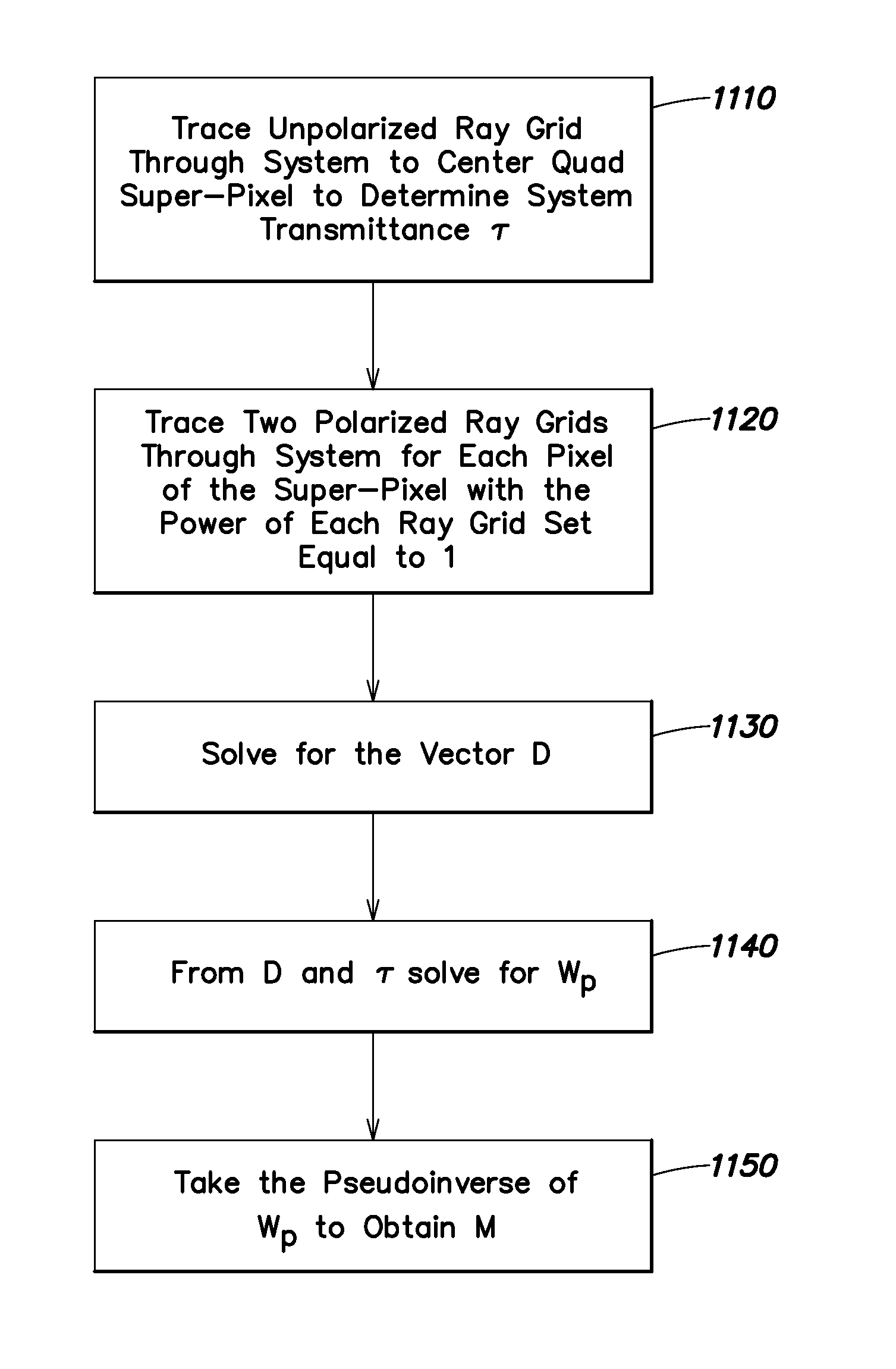
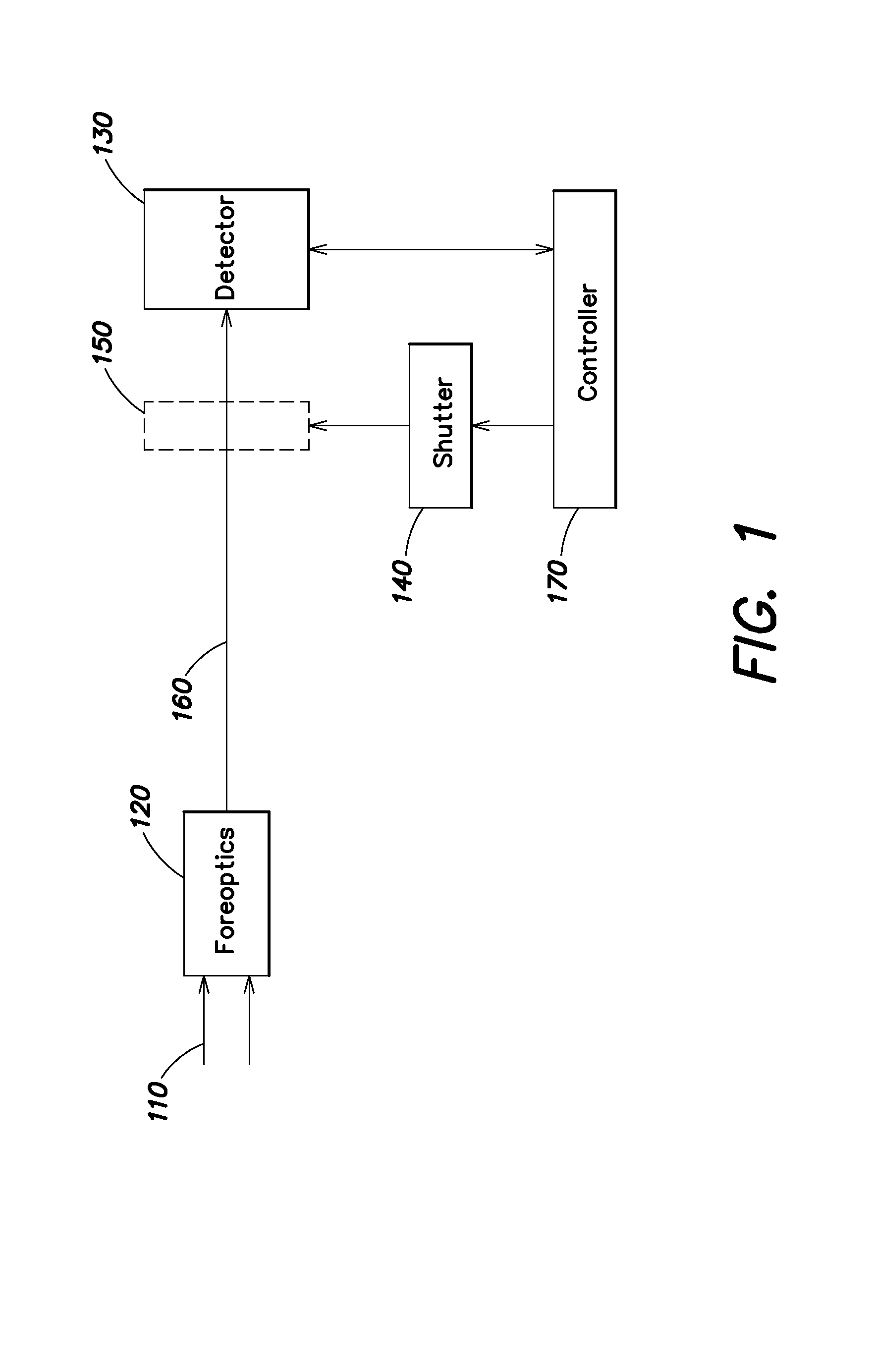
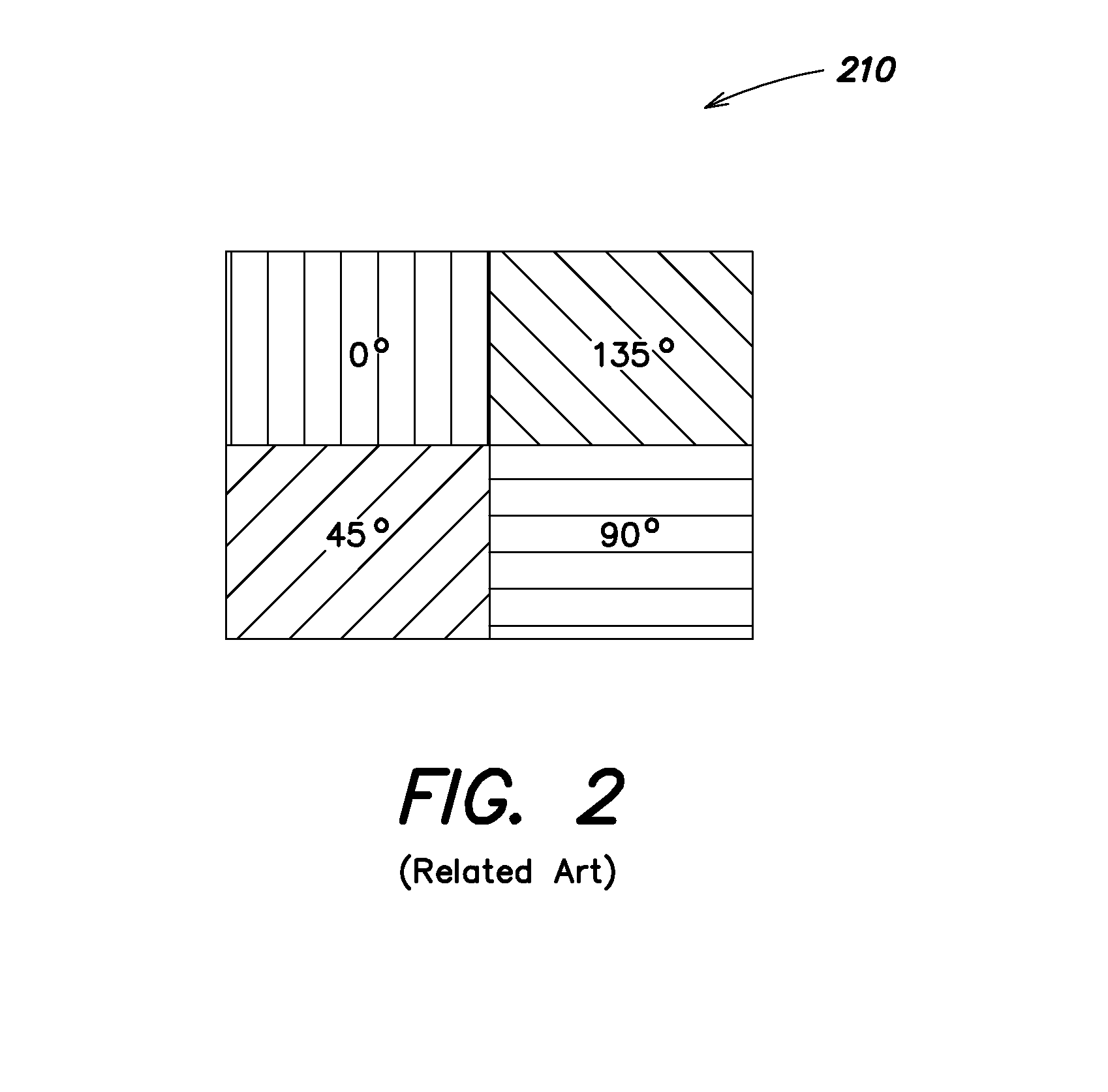
[0021]Aspects and embodiments are directed to imaging systems and methods that incorporate the use of a movable digital pixelated filter array. Embodiments include the combination of a pixelated filter array, which may be a bandpass (e.g., Bayer) filter or polarization filter, a shutter mechanism to which the pixelated filter array is attached, and a data reduction algorithm. As discussed in more detail below, the shutter mechanism allows the pixelated filter array to be moved into and out of the optical path as needed, and the data reduction algorithm allow for axial and / or lateral misalignment of the filter array relative to the imaging detector array or its conjugate. In certain embodiments, the data reduction algorithms also provide the ability to perform wavefront sensing, for example to estimate wavefront error, as also discussed further below. Aspects and embodiments allow pixelated filter arrays to be used in sensitive imaging applications, for example, existing and future m...


PUM


Abstract

An optical imaging system and method including a movable pixelated filter array, a shutter mechanism to which the pixelated filter array is attached, and a controller configured to implement a data reduction algorithm. The shutter mechanism is configured to move the pixelated filter array into and out of the optical path, and the data reduction algorithm allows the controller to account for axial and/or lateral misalignment of the filter array relative to the imaging detector array or its conjugate. In certain examples, the controller is further configured to use the data reduction algorithms also to perform wavefront sensing, for example to estimate wavefront error.

Description

BACKGROUND[0001]Imaging detectors, such as focal plane arrays, generally include an array of pixels, each pixel including a photo-detector that generates a signal responsive to light generated or reflected by an object. These signals are collected and combined such that a digital image of the object can be created. Pixelated filter arrays positioned in a fixed location over the detector array are widely used in commercial imaging systems to provide hyperspectral or polarimetric capability. For example, digital cameras use fixed-in-place pixelated filter arrays for color (RGB) photography. However, these filters reduce the amount of light that reaches the imaging pixel (for example, a red filter reflects blue and green light). Polarimeters can be used to analyze the polarization components of light. Some polarimeters use two or more linear polarizers that filter at least half of the incoming light and direct the remaining light to a focal plane. As a result, the brightness of the ima...

Claims


Application Information

Patent Timeline
Patent Type & Authority Applications(United States)
IPC IPC(8): H04N9/04
CPCG02B5/201G02B5/3025G02B27/285G02B27/286G02B26/007G02B26/023G01J3/513G01J3/0235G01J3/36G01J4/04G01S3/78G01J3/0232G01S3/7803G01S3/781G01S5/16H04N17/002H04N23/11H04N25/134
Inventor FEST, ERICSCHAUB, MICHAEL P.KING, PAGE E.
Owner RAYTHEON CO
Why Eureka
Try Eureka