Emergency lighting control panel

Active Publication Date: 2014-03-06
SCHNEIDER ELECTRIC USA INC
View PDF11 Cites 6 Cited by
  • Summary
  • Abstract
  • Description
  • Claims
  • Application Information

AI Technical Summary

Benefits of technology

[0007]The plurality of automatic load control relays is arranged in the emergency relay electrical enclosure in one or more columns. Wire barriers are positioned at the ends of the columns of relays and between the columns of relays (when two or more columns are present). The wire barriers are designed to work with the bodies or housings of the relays themselves to form channels on both sides of the columns for wires to be run and connected with the relays. On one side of each column of relays is an emergency wire channel for emergency power wires to be run and connected to emergency contacts on the relays and on the other side of each column of relays is a utility wire channel for utility power wires to be run and connected to utility contacts on the relays. Thus, the emergency and utility wire channels—formed by the wire barriers and the columns of relays themselves—aid in keeping the emergency power wires and the utility power wires separate within the emergency relay electrical enclosure as required by the regulations.
[0008]In addition to the wire barriers and the columns of relays forming the wire channels, a cover of the emergency relay electrical enclosure further aids in forming the wire channels by capping and/or sealing the emergency and utility power wires therein. As the cover is coupled to a housing of the emergency relay electrical encl

Problems solved by technology

While such a practice works, it requires a vast amount of wires to be run from the electrical closest in the building—which houses t

Method used


Image

  • Emergency lighting control panel
  • Emergency lighting control panel
  • Emergency lighting control panel

Examples


Example

[0023]Although the invention will be described in connection with certain aspects and / or embodiments, it will be understood that the invention is not limited to those particular aspects and / or embodiments. On the contrary, the invention is intended to cover all alternatives, modifications, and equivalent arrangements as may be included within the spirit and scope of the invention as defined by the appended claims.

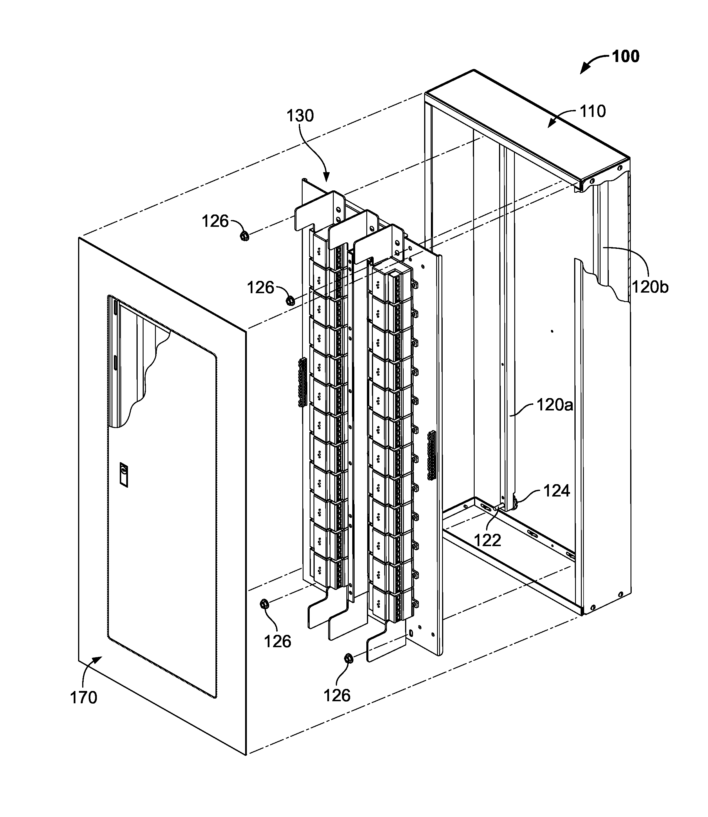
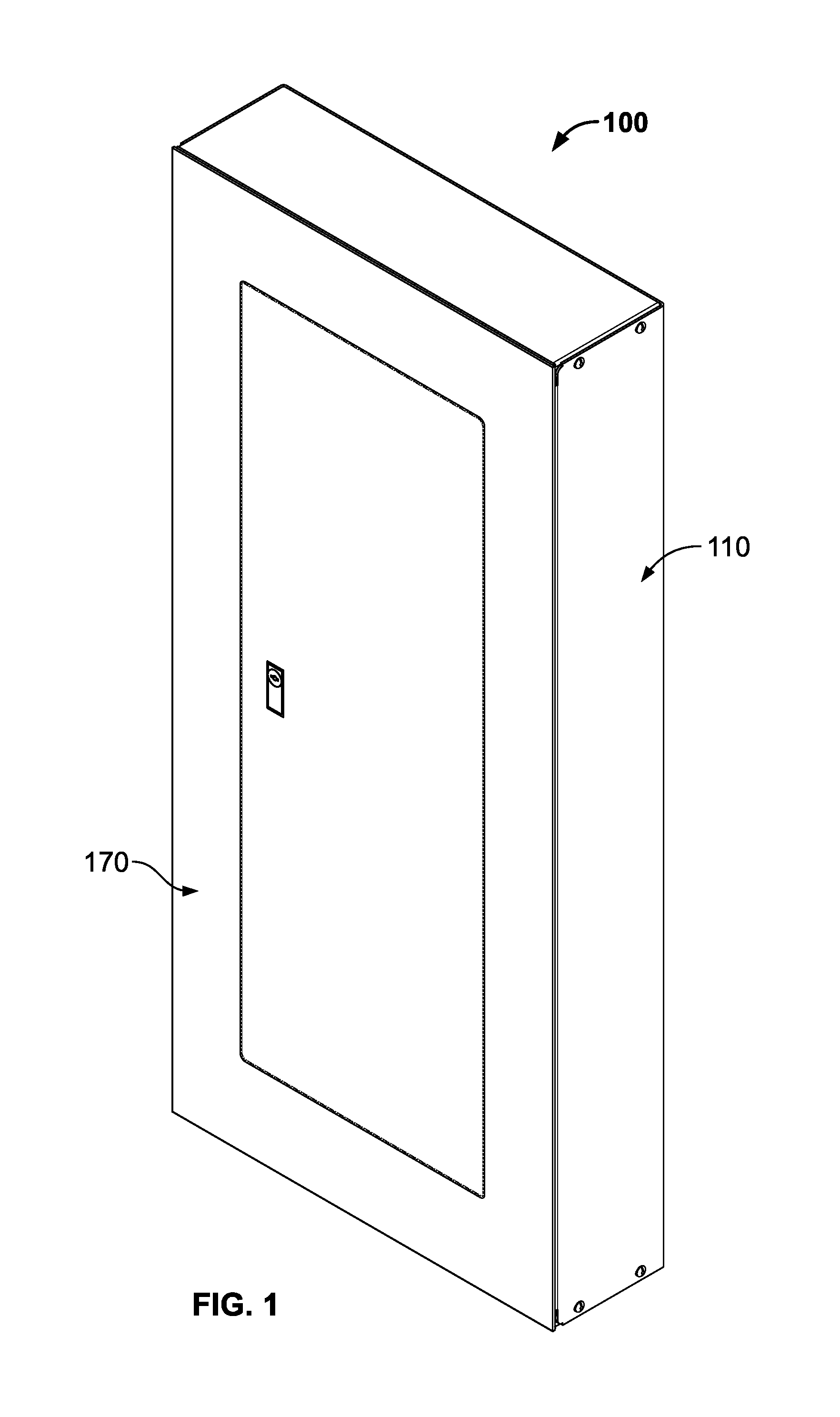
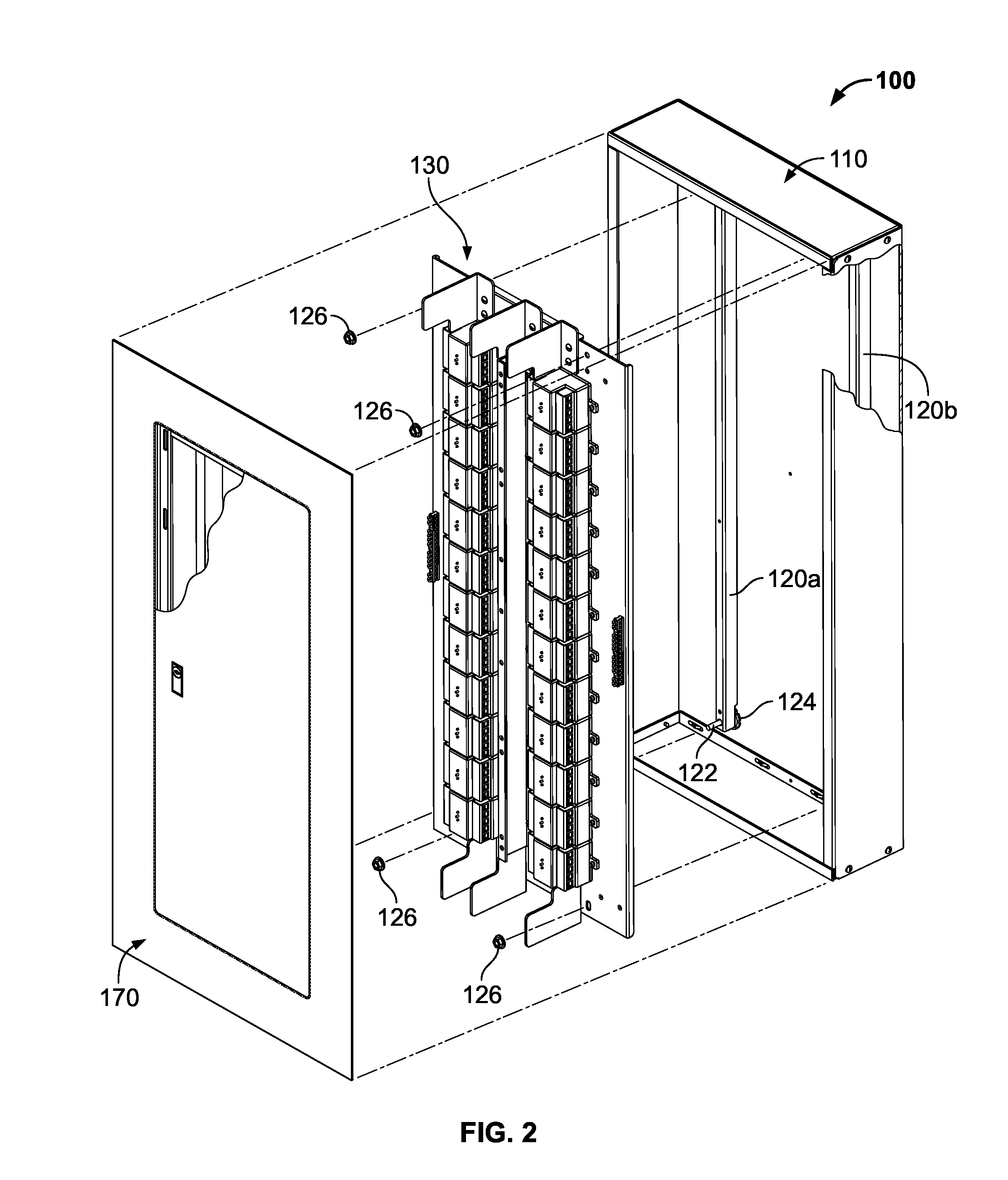
[0024]Referring to FIG. 1, an emergency relay electrical enclosure 100 is shown in the assembled configuration according to the present disclosure. A partially exploded view of the emergency relay electrical enclosure 100 is shown in FIG. 2. Generally, the emergency relay electrical enclosure 100 includes a housing or housing assembly 110, a relay pan assembly 130, and a cover or cover assembly 170. In the assembled configuration (FIG. 1), the relay pan assembly 130 (FIG. 2) is received in and coupled to the housing assembly 110. Further, the cover assembly 170 is coupled t...


PUM


Abstract

A combination emergency panelboard includes a relay section and a circuit-breaker section. The relay section includes automatic load control relays and the circuit-breaker section includes emergency circuit breakers. A dielectric barrier is positioned between the relay and circuit-breaker sections to separate them. A busbar is positioned in the circuit-breaker section for distributing a phase of emergency current to a plurality of emergency circuit breakers coupled thereto. A plurality of automatic load control relays is positioned in the relay section. Each of the relays is electrically connected to a respective one of the plurality of emergency circuit breakers for distributing the phase of emergency current to a respective load.

Description

FIELD OF THE INVENTION[0001]The present invention relates generally to electrical equipment and, more particularly, to emergency lighting electrical enclosures having automatic load control relays therein.BACKGROUND OF THE INVENTION[0002]Electrical enclosures, such as, for example, load centers or panelboards, typically house multiple circuit breakers and / or related electrical accessories for distributing one or more phases of power (e.g., utility power or emergency power) to a plurality of loads (e.g., non-emergency lighting fixtures, emergency lighting fixtures). Automatic load control relays (UL 924 relays) or shunts can be used in emergency lighting schemes or solutions to monitor utility or normal power in a building and automatically turn emergency lighting fixtures on using emergency power from an emergency power panelboard when utility power from a utility power panelboard is interrupted (e.g., power outage).[0003]Regulations restrict the mixing of utility and emergency powe...

Claims


Application Information

Patent Timeline
IPC IPC(8): H02B1/04
CPCH01H2050/049H02B1/205H02B1/42
Inventor MARTIN, HEATH L.JORDAN, SCOTTDYER, JOHN W.
Owner SCHNEIDER ELECTRIC USA INC
Why Eureka
Try Eureka