Tibial insert locking mechanism

a locking mechanism and insert technology, applied in the field of tibial insert locking mechanism, can solve problems such as severe damage, and achieve the effect of preventing disassembly and dislodging during shipping and us

Active Publication Date: 2014-03-06
HOWMEDICA OSTEONICS CORP
View PDF1 Cites 8 Cited by
  • Summary
  • Abstract
  • Description
  • Claims
  • Application Information

AI Technical Summary

Benefits of technology

[0004]This invention relates to a locking mechanism for securing a modular tibial insert to a tibial baseplate to prevent disassociation of the assembly after implantation. The locking mechanism may also be used on tibial trial bearing components. It comprises a locking pin, a spring, a tibial insert, a rec...

Problems solved by technology

Many inserts in the marketplace employ one-way type locking mechanisms for example a snap mechanism using mechanica...

Method used


Image

  • Tibial insert locking mechanism
  • Tibial insert locking mechanism
  • Tibial insert locking mechanism

Examples


Embodiment Construction

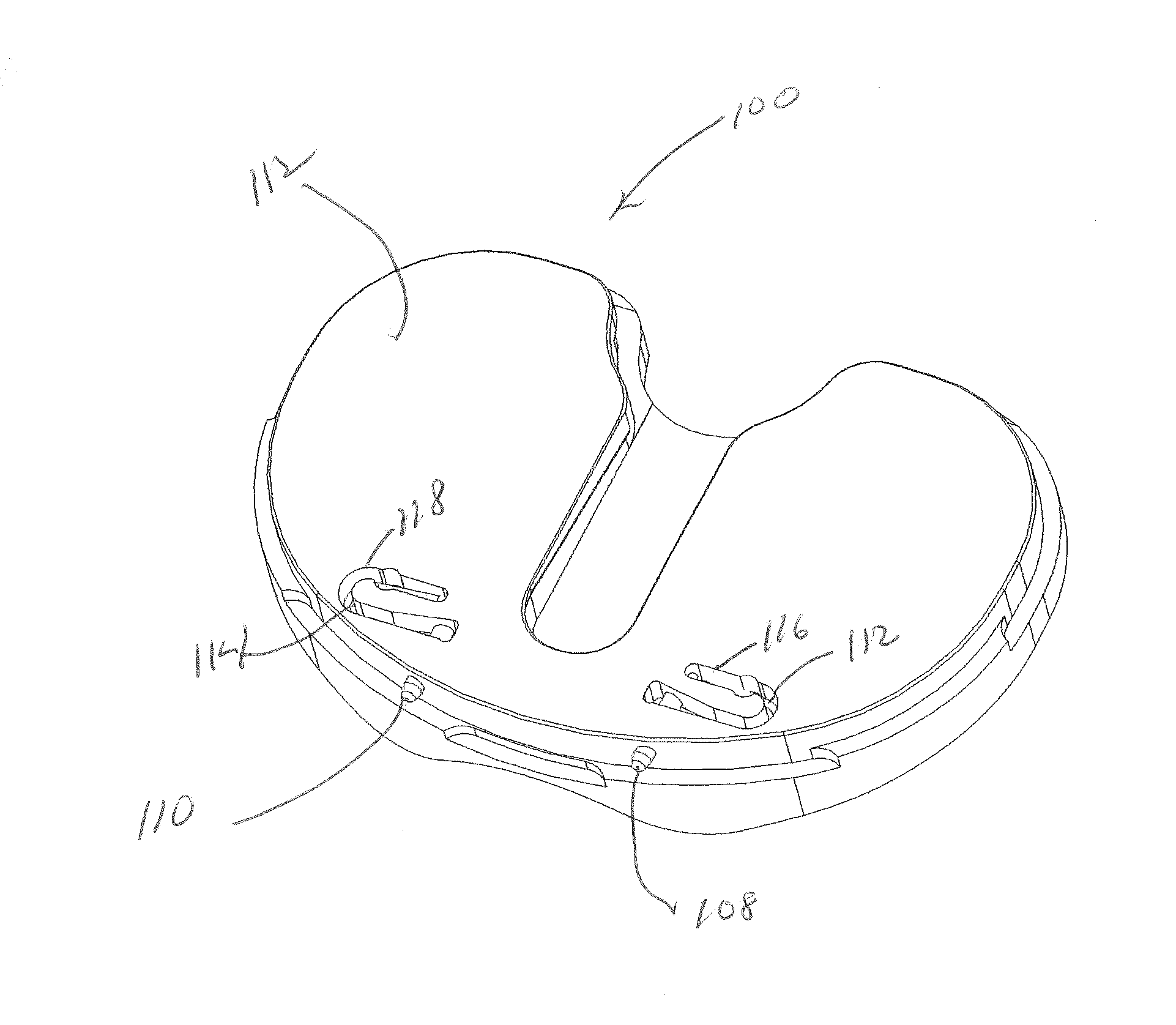
[0023]Referring to FIG. 1, there is shown a bottom view of a tibial bearing insert generally devoted as 10. The insert is preferably made from ultra high molecular weight polyethylene (UHMWPE). The view of insert 10 as shown in FIG. 1 is a bottom view of a single condylar portion of a prosthetic tibial implant. While only one condylar portion is shown, the bearing insert 10 may be comprised of two (medial and lateral) bearing inserts which can be separate or can be joined together along an anterior bridge portion (not shown). The proximally facing surface of the tibial implant, best seen in FIG. 5, contains the prosthetic condylar bearing surface adapted to engage a corresponding condyle on the prosthetic femoral component (not shown). The insert 10 is preferably mounted on a metal tibial baseplate, or tibial tray in any conventional manner.

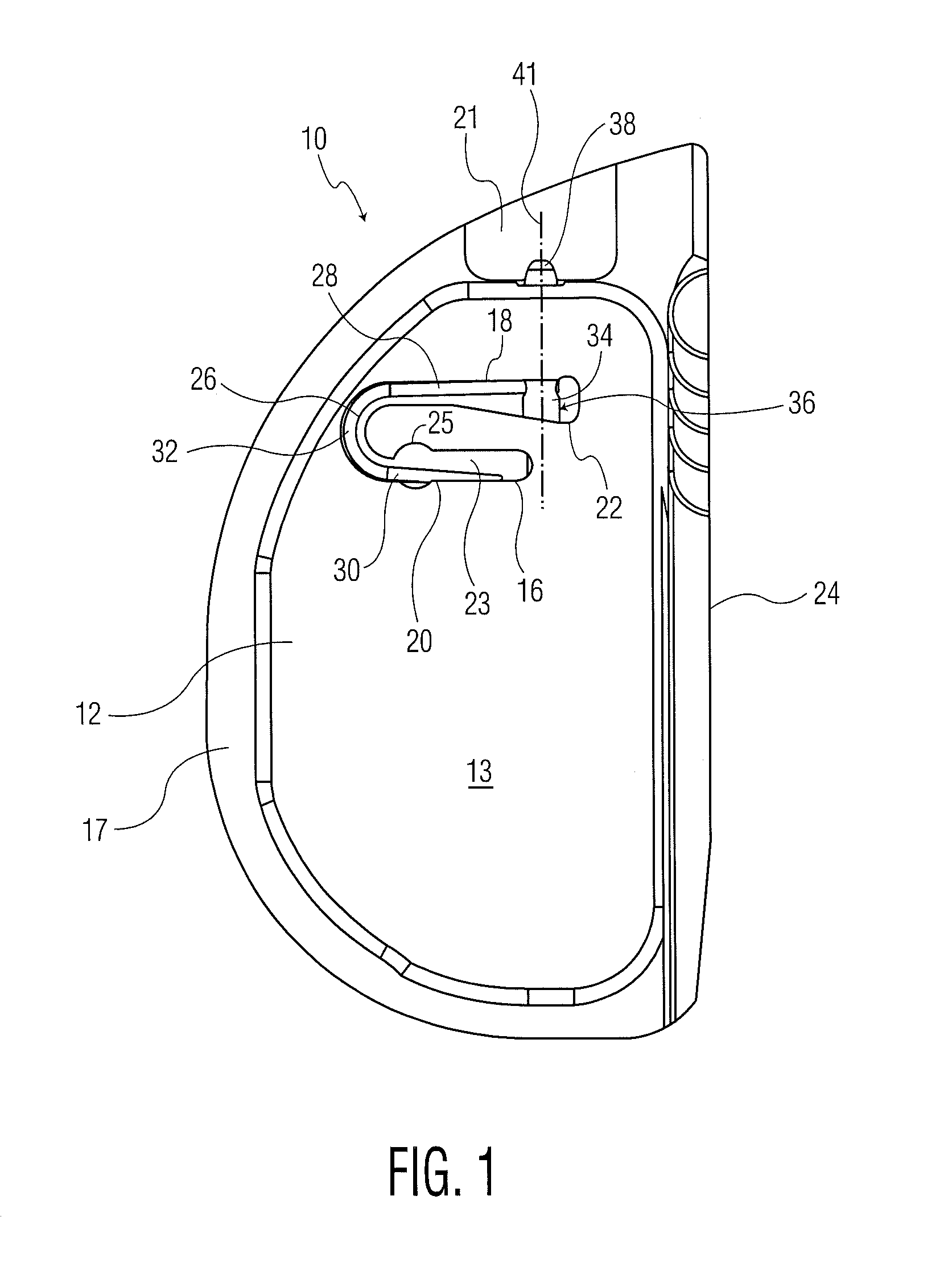
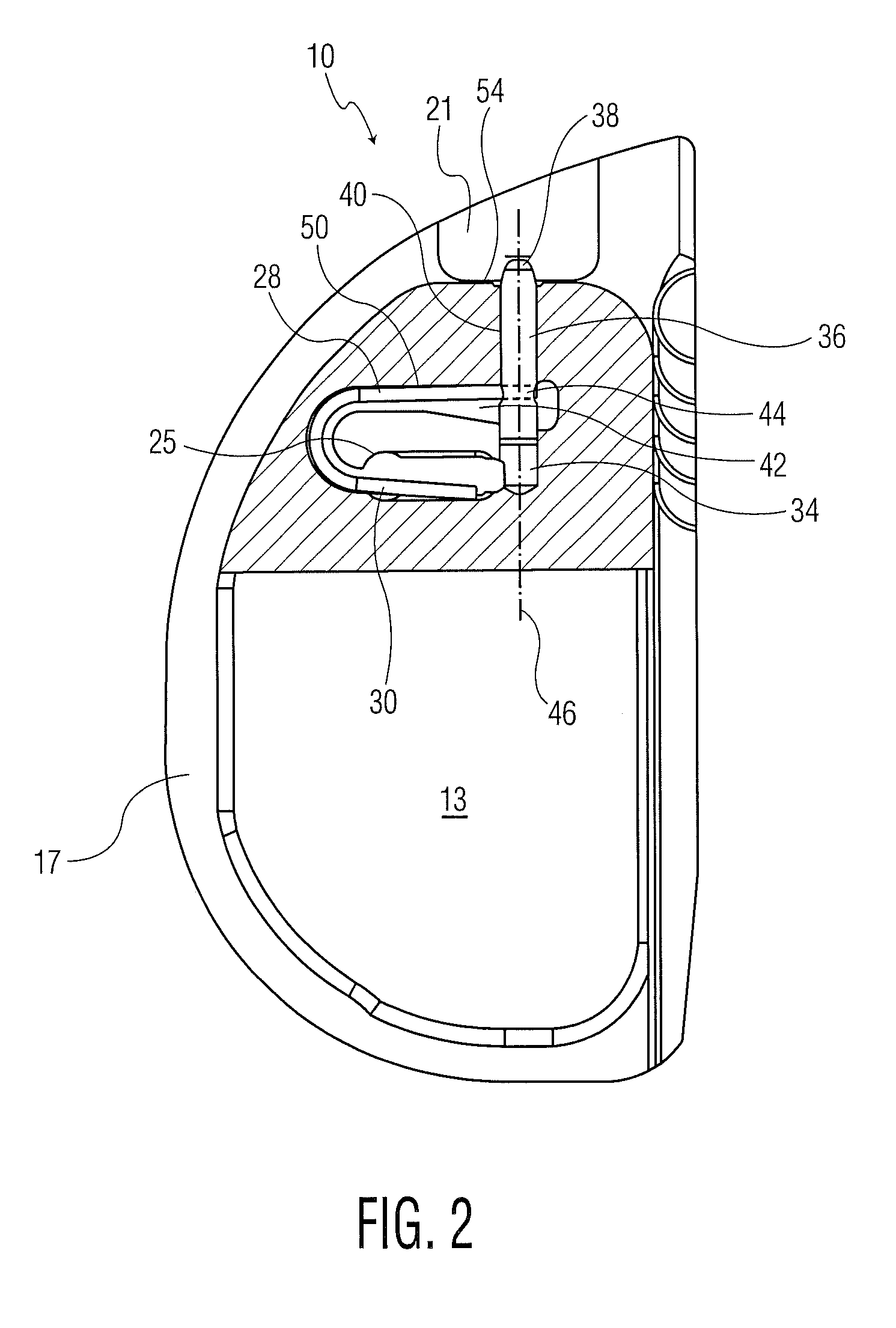
[0024]As can be seen in FIG. 1, a distal surface 12 is formed on a boss 13 extending from a distally facing shelf surface 17 which extends aroun...


PUM


Abstract

A tibial implant includes a baseplate having a proximally facing surface surrounded at least in part by a proximally extending wall. The wall has a ramp surface extending from the wall towards the baseplate proximally facing baseplate surface and a bore located distally of the ramp. A polyethylene bearing insert is mounted on the baseplate and has a distally facing surface engaging the proximally facing surface of the baseplate. The distally facing bearing insert surface has a recess and the insert has a side surface with a passageway extending from the recess through the insert side surface. A spring detent is mounted in the bearing insert recess and has a moveable pin biased outwardly of the bearing insert side surface and into the bore of the baseplate.

Description

BACKGROUND OF THE INVENTION[0001]Artificial joints of the human body, including in particular knee and hip joints, have been available for 50 years or more and have been the subject of intense development for at least the last 20 years. The earliest designs provided metal-to-bone or metal-to-metal contact between the articulating surfaces of a joint. Friction and wear were significantly reduced in subsequent designs by the introduction of ultra-high molecular weight polyethylene (UHMWPE) as a load-bearing surface. For example, a typical knee joint prosthesis has a metal tibial component or baseplate with a polyethylene load-bearing surface in contact with a metal femoral component. Early designs of this type had polyethylene cemented to the tibia, but it is conventional today to secure a polyethylene bearing to a metal base or tray which is anchored in the tibia, typically with the aid of a stem or peg extending into the medullary canal of the tibia.[0002]There are two general types...

Claims


Application Information

Patent Timeline
IPC IPC(8): A61F2/38
CPCA61F2/389A61F2002/30616
Inventor COLLAZO, CARLOS E.
Owner HOWMEDICA OSTEONICS CORP
Why Eureka
Try Eureka