
Pyrolysis vapor rapid filtration and conversion to fuel

Inactive Publication Date: 2014-03-13
PHILLIPS 66 CO
View PDF2 Cites 2 Cited by
  • Summary
  • Abstract
  • Description
  • Claims
  • Application Information

AI Technical Summary

Benefits of technology

The patent processes and systems solve the problem of catalyst fouling and poisoning over time, preventing the blockages of catalyst beds that receive pyrolysis vapors carrying char particles. Additionally, these processes and systems minimize the delay between producing the pyrolysis vapors and upgrading them to products that can be used as fuel.

Problems solved by technology

Conventional pyrolysis methods and systems have suffered from either 1) char carry-over in the pyrolysis vapors, leading to deactivation of downstream upgrading catalysts, or 2) use of separation devices such as conventional filter and cyclones to remove char from pyrolysis vapors, which results in an undesirable delay prior to either quenching or catalytically upgrading the pyrolysis vapors.
Such delay can allow undesirable secondary reactions to occur that produce excessively large molecular weight products that are difficult to further upgrade into a transportation fuel.

Method used


Image

  • Pyrolysis vapor rapid filtration and conversion to fuel
  • Pyrolysis vapor rapid filtration and conversion to fuel
  • Pyrolysis vapor rapid filtration and conversion to fuel

Examples


Embodiment Construction

[0014]Pyrolysis vapors are known to be highly reactive, and can rapidly form high molecular weight compounds that are above the boiling-point range of typical hydrocarbon transportation fuels (i.e., a carbon number greater than about 35). Examples of typical addition reactions between compounds typically found in pyrolysis vapors are shown in Schemes 1-3 below:

Scheme 1: Reaction of Propionaldehyde (C3) and Methyl Furan (C5) to Form a C11 Molecule.

[0015]

Scheme 2: Reaction of Propylene (C3-) and a Vinyl Cresol (C9) to Form a C12 Molecule.

[0016]

Scheme 3: Reaction of a Vinyl Cresol (C9) and a Dimethoxy Vinyl Phenol (C10) to Form a C19 Molecule.

[0017]

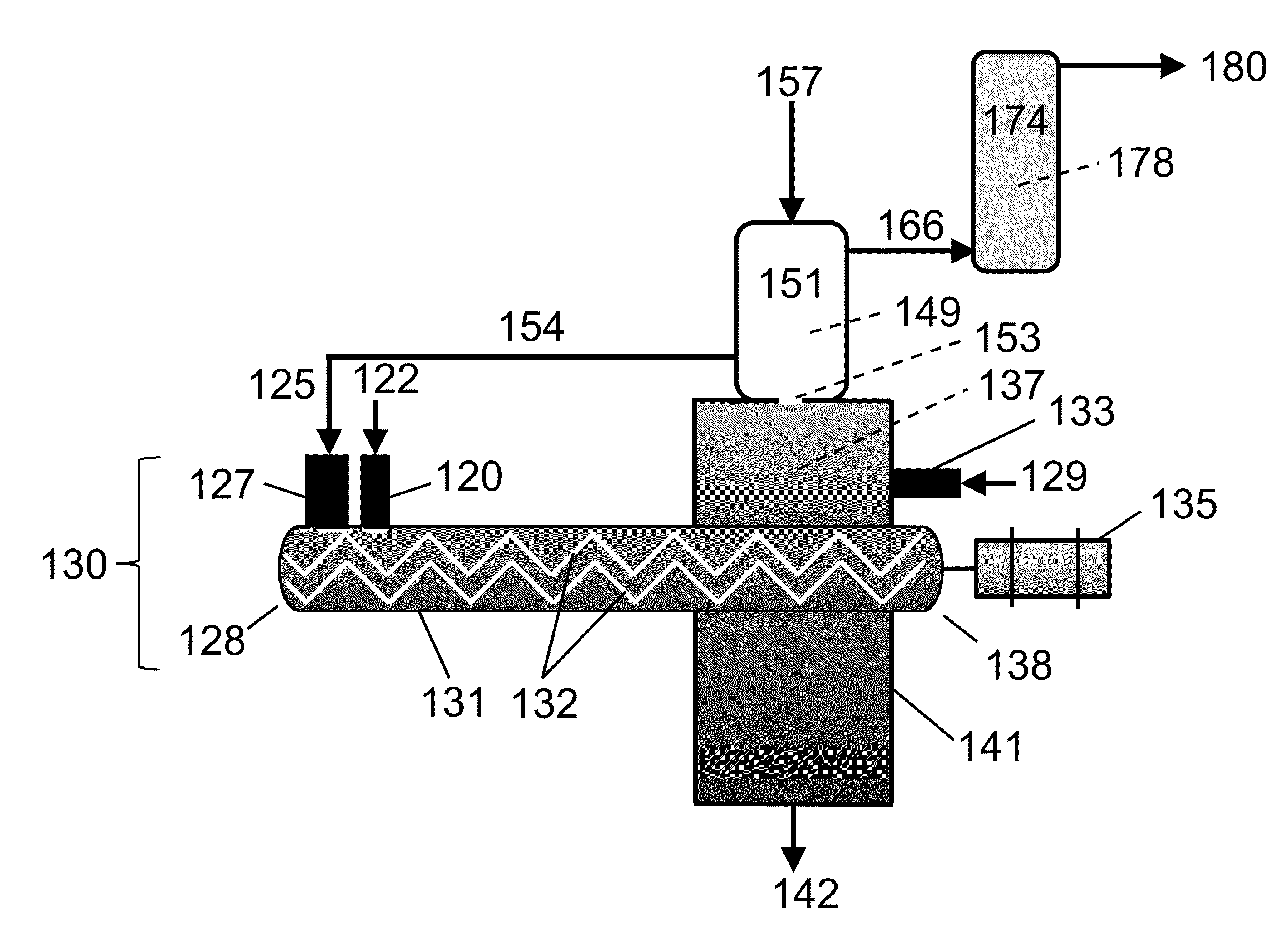
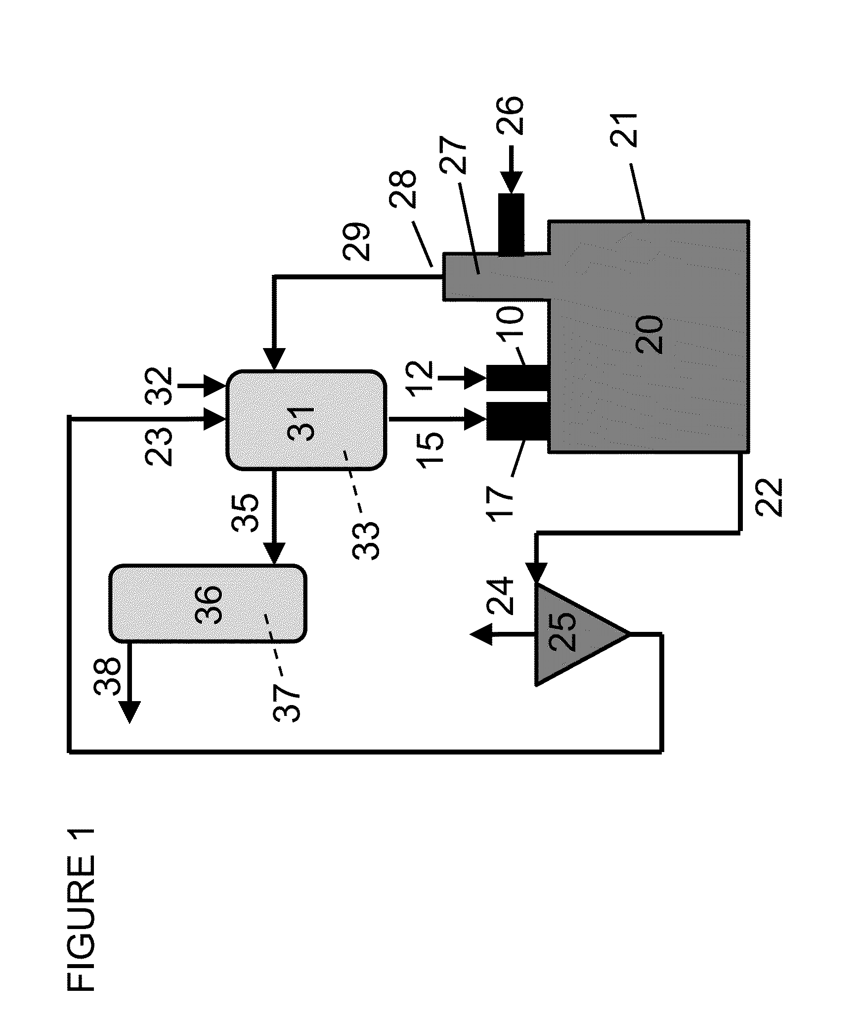
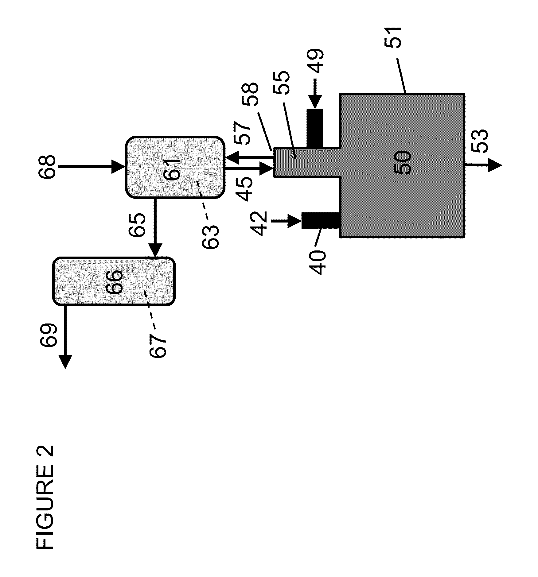
[0018]The methods and systems described herein allow rapid filtration / removal of solid char particles from raw pyrolysis vapors by immediately directing the vapors through a moving bed granular filter (MBGF) comprising a heated heat carrier as the granular filter material. The heated heat carrier slowly passes through the MBGF and is conveye...


PUM

PropertyMeasurementUnit
Temperatureaaaaaaaaaa
Flow rateaaaaaaaaaa

Abstract

The present disclosure pertains to biomass pyrolysis processes and systems that decrease entrainment of char and other contaminants in the pyrolysis vapors by filtering the vapors in a heated container comprising a moving bed granular filter (MBGF), which in turn, comprises granular heat carrier. The granular heat carrier is heated within the MBGF and fed directly to the pyrolysis reactor, optionally along with filtered solids such as char. In certain embodiments, the MBGF additionally comprises at least one upgrading catalyst that contacts the vapors to produce a hydrocarbon mixture fungible with a petroleum-derived transportation fuel, a hydrocarbon transportation fuel component, or mixtures thereof.

Description

CROSS-REFERENCE TO RELATED APPLICATIONS[0001]This application is a non-provisional application which claims benefit under 35 USC §119(e) to U.S. Provisional Application Ser. No. 61 / 699,000 filed Sep. 10, 2012, entitled “Generating Deoxygenated Pyrolysis Vapors,” which is incorporated herein in its entirety.STATEMENT REGARDING FEDERALLY SPONSORED RESEARCH OR DEVELOPMENT[0002]None.FIELD OF THE DISCLOSURE[0003]This disclosure relates to systems and methods for the fast pyrolysis of organic matter to produce transportation fuel. More specifically, it relates to the rapid removal of entrained char particulates from pyrolysis vapors, and optionally, catalytic modification of pyrolysis vapors created during the fast pyrolysis of organic matter to create a hydrocarbon transportation fuel or a component thereof.BACKGROUND[0004]The U.S. Renewable Fuel Standards (RFS) mandate requires increasing volumes of advanced biofuels to be produced. One method being developed to meet this mandate is the...

Claims


Application Information

Patent Timeline
IPC IPC(8): C10G1/00
CPCC10G1/002C10K1/30C10K3/02C10B49/16C10B53/02C10G2300/1011C10G2/32C10G3/55C10G3/42Y02P20/145Y02P30/20C10G1/02Y02E50/30Y02E50/10C10J3/52
Inventor JONES, SAMUEL T.GORKE, JONATHAN T.HUGHES, MARK A.
Owner PHILLIPS 66 CO
Learn More