Process for producing high-carbon biogenic reagents

a biogenic reagent and process technology, applied in chemical/physical processes, energy input, energy-based wastewater treatment, etc., can solve the problems of high energy consumption, high cost, and environmental pollution of traditional charcoal-making technologies, and achieve the effect of increasing carbon content and/or energy conten

Active Publication Date: 2014-03-20
CARBON TECH HLDG LLC
View PDF4 Cites 20 Cited by
  • Summary
  • Abstract
  • Description
  • Claims
  • Application Information

AI Technical Summary

Benefits of technology

[0030]In some embodiments, the process includes monitoring and controlling the process with at least one reaction gas probe, such as two or more reaction gas probes. Monitoring and controlling the process can improve process energy efficiency. Monitoring and controlling the process can also improve a product attribute associated with the high-carbon biogenic reagent, such as (but not limited to) carbon content, energy content, structural integrity, or mechanical strength.
[0160]In some embodiments, the process additive and / or the product additive is selected to increase the carbon content and / or the energy content of the high-carbon biogenic reagent. In some embodiments, the process additive and / or the product additive is selected to maintain the structural integrity or mechanical strength of the high-carbon biogenic reagent relative to said feedstock. Additives may be useful to help maintain structural form prior to use of the biogenic reagent.

Problems solved by technology

Converting biomass to high-carbon reagents, however, poses both technical as well as economic challenges arising from feedstock variations, operational difficulties, and capital intensity.
Traditional charcoal-making technologies are energy-inefficient as well as highly polluting.
Clearly, there are economic and practical challenges to scaling up such a process for continuous commercial-scale production of high-quality carbon, while managing the energy balance and controlling emissions.

Method used


Image

  • Process for producing high-carbon biogenic reagents
  • Process for producing high-carbon biogenic reagents
  • Process for producing high-carbon biogenic reagents

Examples


example 1

Preparation of Biogenic Reagent—General Method

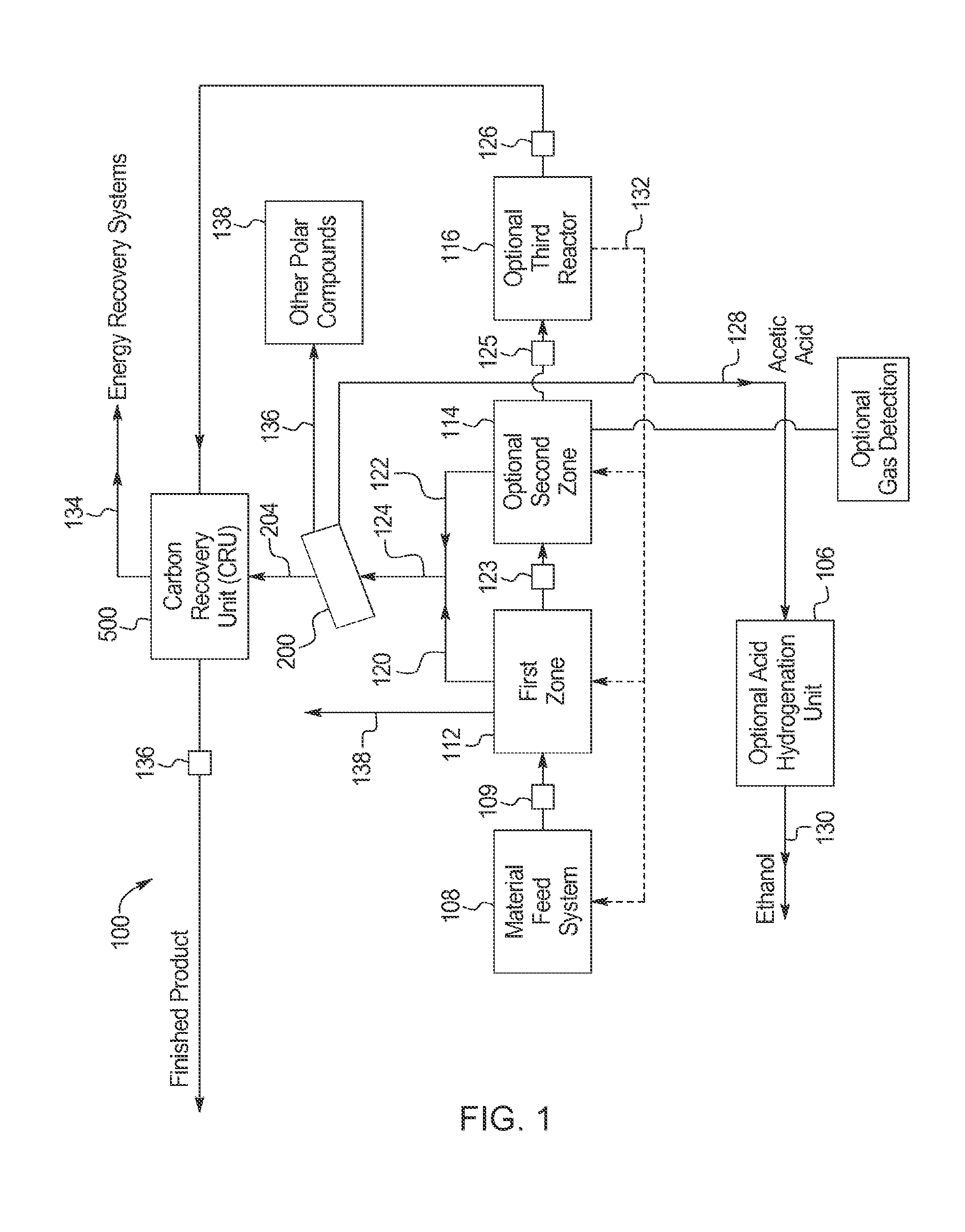
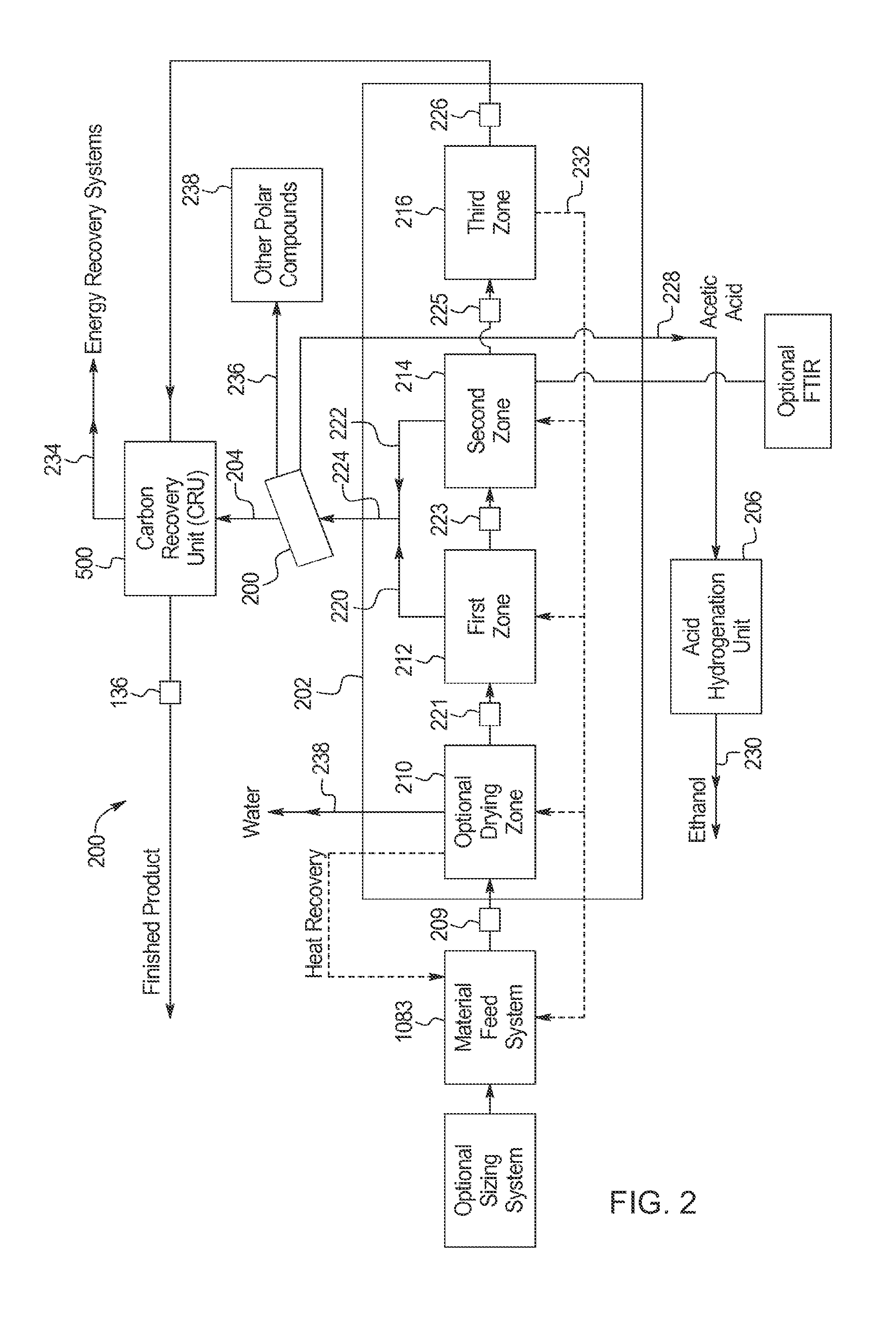
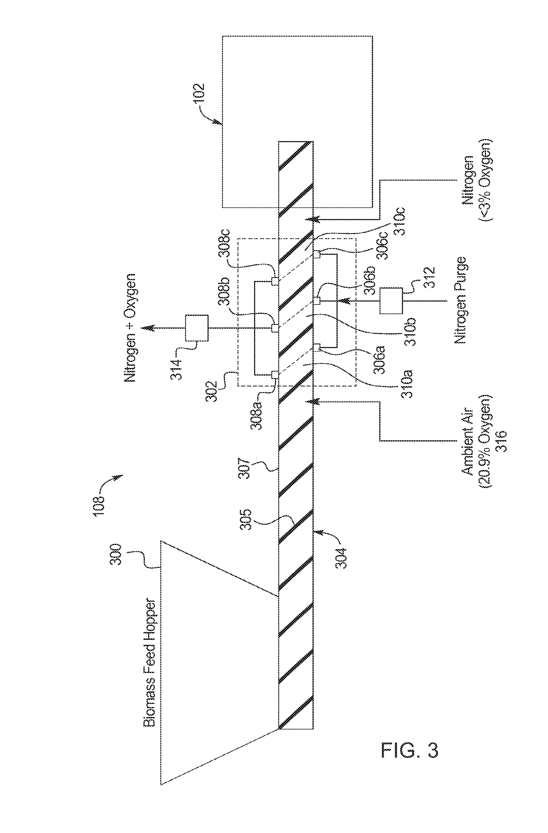
[0612]Wood substrate red pine large chips, Douglas fir cylinders (1.25-inch diameter pieces) and Douglas fir pieces (approximately 2 inches by 2 inches), were loaded into a loading hopper having an optionally heated nitrogen gas flow. Optionally, a 1% aqueous solution of an additive (e.g., NaOH and / or KOH) was applied by spray to the wood substrate while in the hopper or by soaking the biomass in the aqueous additive solution. Regardless of the application method, the additive solution was allowed to penetrate the biomass for 30 minutes before the biomass was dried. Once the reactor had reached the desired temperature, rotation of the reactor was initiated and the wood substrate was fed slowly by activating the material feed system. Average residence times in the heated portion of the reactor for each batch are indicated in Table 1. After exiting the heated portion of the reactor, the pyrolyzed material collected in a discharge hopper. A...

example 2

Analysis of Biogenic Reagent

[0614]Parameters of the biogenic reagents prepared according to the General Method of Example 1 were analyzed according to Table 2 below.

TABLE 2Methods Used to Analyze Biogenic Reagents.ParameterMethodMoisture (total)ASTM D3173Ash contentASTM D3174Volatile Matter contentASTM D3175Fixed Carbon content (by calculation)ASTM D3172Sulfur contentASTM D3177Heating Value (BTU per pound)ASTM D5865Carbon contentASTM D5373Hydrogen contentASTM D5373Nitrogen contentASTM D5373Oxygen content (by calculation)ASTM D3176

[0615]Results for Samples A through F, which were prepared without the use of additives, are shown in Table 3 below.

TABLE 3Characteristics of Biogenic Reagents A Through F.SampleABCDEFMoisture (wt. %)2.423.023.510.4780.8644.25Ash (wt. %)1.160.9170.8391.031.061.43Volatile Matter (wt. %)38.746.442.82.817.018.4Fixed Carbon (wt. %)57.749.452.995.781.076.0Sulfur (wt. %)ND†NDNDNDNDNDHeat Value (BTU / lb.)12,80712,45212,34614,70013,98313,313Carbon (wt. %)73.371.271....

example 3

Production of a High Heat Value Biogenic Reagent

[0617]This example demonstrates production of a biogenic reagent having a high heat value.

[0618]A feedstock comprising Douglas fir cylindrical pieces (1⅛″ diameter, approx. 1.5-inch lengths) was pyrolyzed according to the General Method of Example 1. The reactor was heated to 600° C. and the feedstock was pyrolyzed with a residence time of 30 minutes. After cooling, the resulting biogenic reagent was analyzed according to the methods described in Example 2. Results are shown in Table 5.

TABLE 5Analysis of High Heat Value Biogenic Reagent.ASTMAsh &ParameterMethodAs-ReceivedMoisture FreeMoisture FreeProximate AnalysisMoistureD31731.45 wt. %——(total)AshD31740.829 wt. % 0.841 wt. % —VolatileD31757.15 wt. %7.26 wt. %7.32 wt. %MatterFixedD317290.6 wt. %91.9 wt. %92.7 wt % CarbonSulfurD3177ND†NDNDHeat ValueD586514,942 BTU / lb15,162 BTU / lb15,291 BTU / lbUltimate AnalysisMoistureD31731.45 wt. %——(total)AshD31740.829 wt. % 0.841 wt. % —SulfurD3177ND...


PUM

PropertyMeasurementUnit
temperatureaaaaaaaaaa

Abstract

This invention provides processes and systems for converting biomass into high-carbon biogenic reagents that are suitable for a variety of commercial applications. Some embodiments employ pyrolysis in the presence of an inert gas to generate hot pyrolyzed solids, condensable vapors, and non-condensable gases, followed by separation of vapors and gases, and cooling of the hot pyrolyzed solids in the presence of the inert gas. Additives may be introduced during processing or combined with the reagent, or both. The biogenic reagent may include at least 70 wt %, 80 wt %, 90 wt %, 95 wt %, or more total carbon on a dry basis. The biogenic reagent may have an energy content of at least 12,000 Btu / lb, 13,000 Btu / lb, 14,000 Btu / lb, or 14,500 Btu / lb on a dry basis. The biogenic reagent may be formed into fine powders, or structural objects. The structural objects may have a structure and / or strength that derive from the feedstock, heat rate, and additives.

Description

FIELD OF THE INVENTION[0001]The present invention generally relates to processes, systems, and apparatus for the production of high-carbon biogenic reagents, and compositions, products, and uses related thereto.BACKGROUND OF THE INVENTION[0002]Carbon is a platform element in a wide variety of industries and has a vast number of chemical, material, and fuel uses. Carbon is a good fuel to produce energy, including electricity. Carbon also has tremendous chemical value for various commodities and advanced materials, including metals, metal alloys, composites, carbon fibers, electrodes, and catalyst supports. For metal making, carbon is useful as a reactant, for reducing metal oxides to metals during processing; as a fuel, to provide heat for processing; and as a component of the final metal alloy. Carbon is a very important element in steel since it allows steel to be hardened by heat treatment.[0003]Carbon-based reagents can be produced, in principle, from virtually any material conta...

Claims


Application Information

Patent Timeline
Patent Type & Authority Applications(United States)
IPC IPC(8): C10L5/44
CPCC10L5/447C10B49/02C10B53/02C10B57/02C10L5/04C10B47/30C21B5/007Y02W10/30Y02W10/37C21B13/0066Y02P20/129Y02P10/143C10L2290/145C10L2290/50C10L2290/58C10L2290/60C10L5/363C10L2290/02C10L2290/08C10L2290/30C10L2290/52H01B1/04C01B32/318Y02P20/133Y02E50/10Y02E50/30Y02E60/10Y02P20/145C10L5/365C10L5/366C10L2200/0204C10L2200/025C10L2200/0469C10L2290/06C10L2290/28C22B4/02C10B39/02C10B41/00C10B57/06C10B57/10C10B45/00B01J21/18C10B39/00C10B43/02C10L5/36C10L5/442C21C5/52C01B32/312
Inventor MENNELL, JAMES A.DESPEN, DANIEL J.
Owner CARBON TECH HLDG LLC
Why Eureka
Try Eureka