

Imaging lens and imaging apparatus
- Summary
- Abstract
- Description
- Claims
- Application Information
AI Technical Summary
Benefits of technology
Problems solved by technology
Method used
Image

Examples
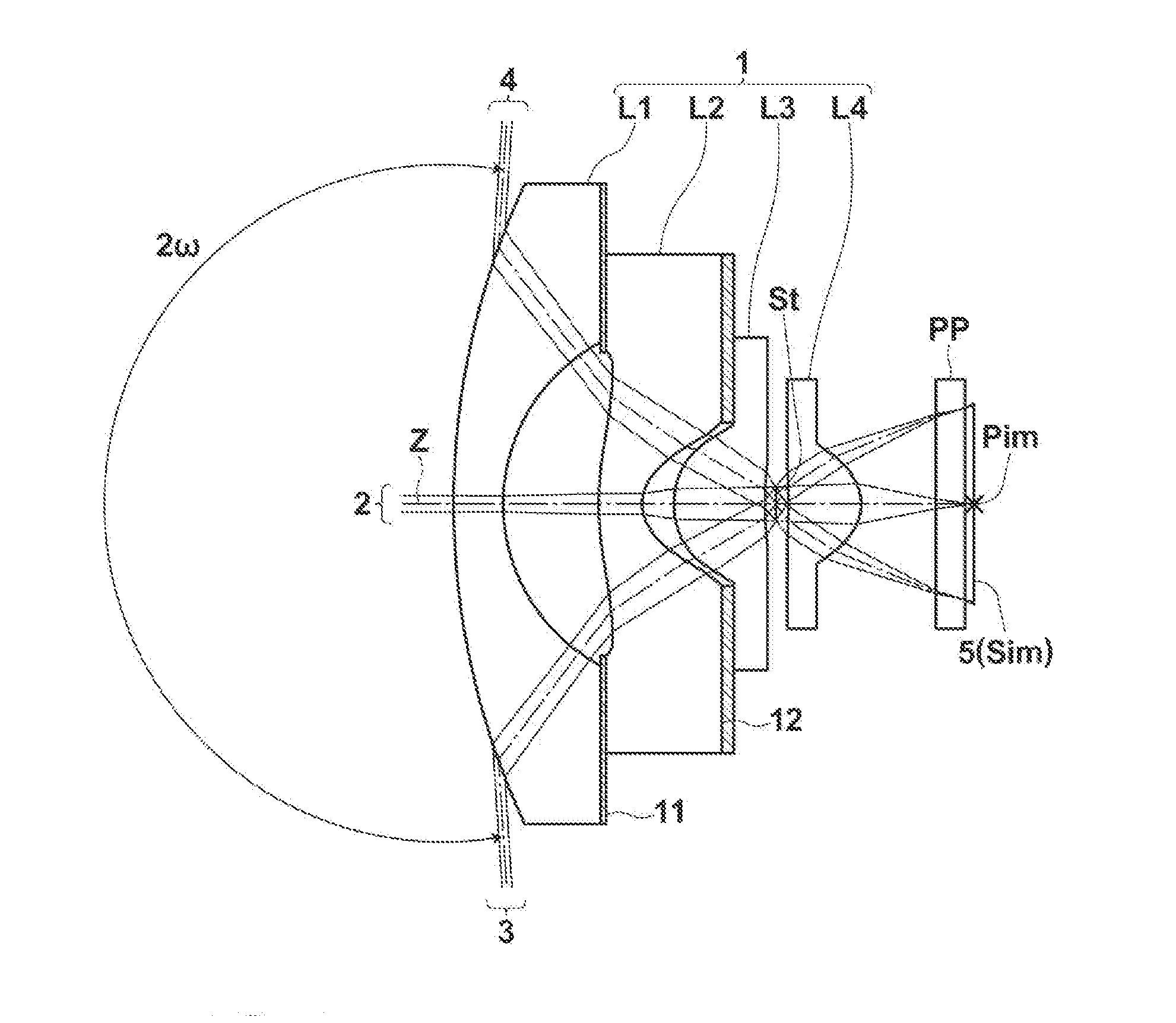
first embodiment
[0135]The imaging lens according to the present invention satisfies the following conditional foimula:
2.25<νd2 / νd3 (1), where
[0136]νd2: an Abbe number of a material of second lens L2 for d-line, and
[0137]νd3: an Abbe number of a material of third lens L3 for d-line.
[0138]When the lower limit of conditional formula (1) is satisfied, it is possible to easily correct a lateral chromatic aberration.
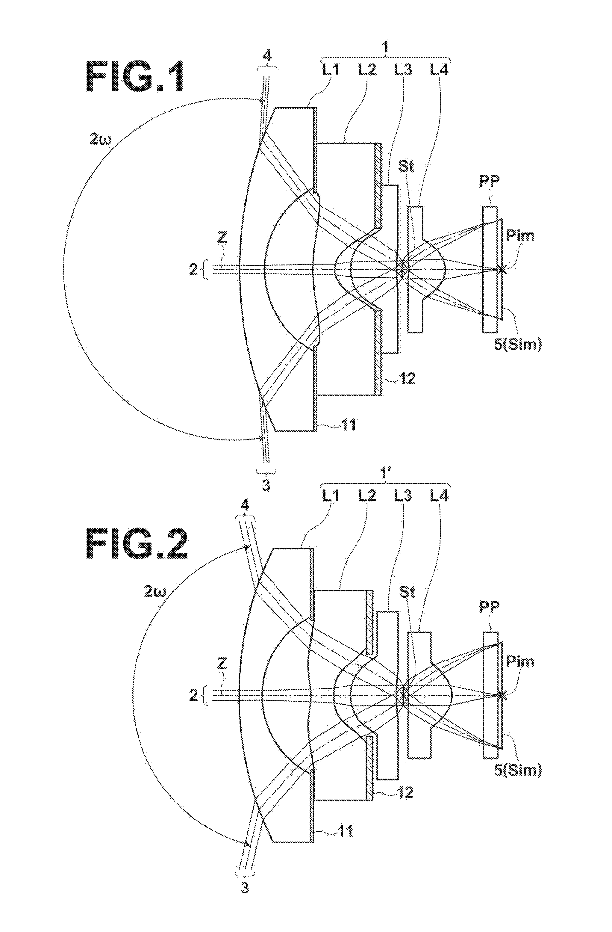
[0139]Next, the structure of the second embodiment of the present invention will be described. An imaging lens according to the second embodiment of the present invention includes negative first lens L1, negative second lens L2, third lens L3 of a plane-convex shape having a convex surface directed toward an object side or of a positive meniscus shape having a convex surface directed toward the object side, and fourth lens L4 of a plane-convex shape having a convex surface directed toward an image side or of a positive meniscus shape having a convex surface directed toward the image side,...
second embodiment
[0142]The imaging lens according to the present invention satisfies the following conditional formula (2):
0.09<Nd3−Nd2 (2), where
[0143]Nd2: a refractive index of a material of second lens L2 for d-line, and
[0144]Nd3: a refractive index of a material of third lens L3 for d-line.
[0145]When the lower limit of conditional formula (2) is satisfied, it is possible to increase the refractive index of third lens L3. Therefore, it is possible to easily increase the power of third lens L3, and to easily correct a lateral chromatic aberration and curvature of field, or it is possible to prevent the refractive index of second lens L2 from becoming too high, and to prevent the Abbe number of the material of second lens L2 from becoming too small. Therefore, correction of chromatic aberrations becomes easy.
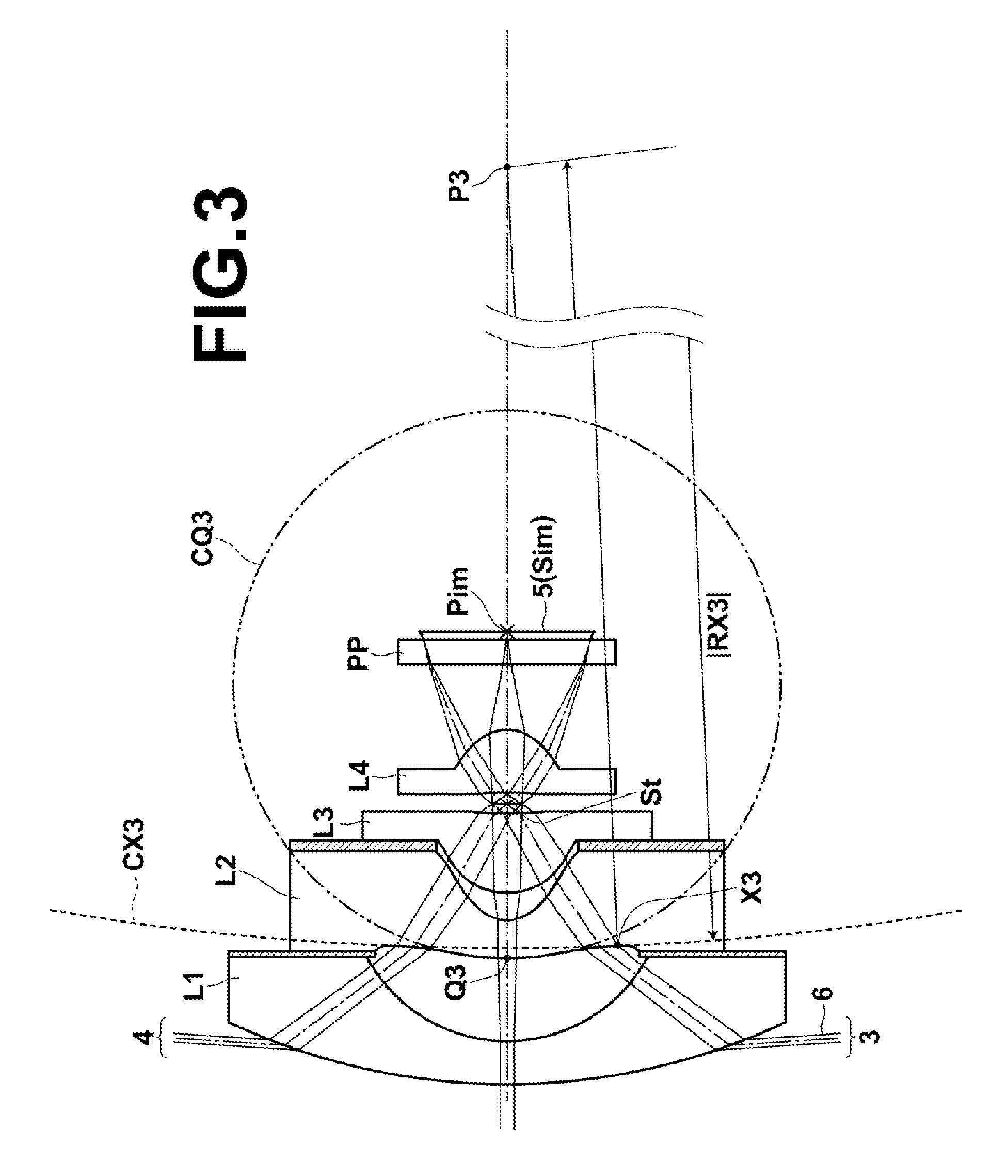
[0146]Next, the structure of the third embodiment of the present invention will be described. An imaging lens according to the third embodiment of the present invention includes negative fi...
third embodiment
[0150]The imaging lens according to the present invention satisfies the following conditional formula (8):
8.0<L / f<13.9 (8), where
[0151]L: a distance from a vertex of an object-side surface of first lens L1 to an image plane, and
[0152]f: a focal length of an entire system.
[0153]When the upper limit of conditional formula (8) is satisfied, it is possible to easily reduce the size of the lens system. If the value is lower than the lower limit of conditional formula (8), a focal length becomes too long, and it becomes difficult to achieve a wide angle of view, or distortion becomes too large by widening an angle of view. Further, an image in a peripheral area is formed in small size, or the size of the lens system becomes too small. Consequently, the thickness of each lens and a distance between lenses become small. Therefore, production becomes difficult, and that causes an increase in cost.
[0154]Next, the structure of the fourth embodiment of the present invention will be descr...
PUM
 Abstract
Description
Claims
Application Information