
Charging member, process cartridge and electrophotographic apparatus

a technology of electrophotography and process cartridges, applied in the direction of corona discharge, instruments, coatings, etc., can solve the problems of difficult stable and uniform charging in some cases, abnormal discharge in some cases, etc., and achieve the effect of forming a high-quality electrophotographic image and reducing contamination

Inactive Publication Date: 2014-03-20
CANON KK
View PDF4 Cites 29 Cited by
  • Summary
  • Abstract
  • Description
  • Claims
  • Application Information

AI Technical Summary

Benefits of technology

The invention is about a charging member that can prevent uneven charging when printing using electrophotography. It also has minimal contamination on its surface and can produce consistent charging over a long period of time. This invention results in high quality printed images.

Problems solved by technology

However, according to studies by the present inventors, with respect to the charging member described in Japanese Patent Application Laid-Open No. 2001-173641, fine electron deficiencies present in the organic-inorganic hybrid film have caused abnormal discharge in some cases.
In addition, with respect to the conductive roller described in Japanese Patent Application Laid-Open No. 2010-197590, an ionic substance has bled out at the time of repeatedly outputting an image, thereby making stable and uniform charging difficult in some cases.

Method used


Image

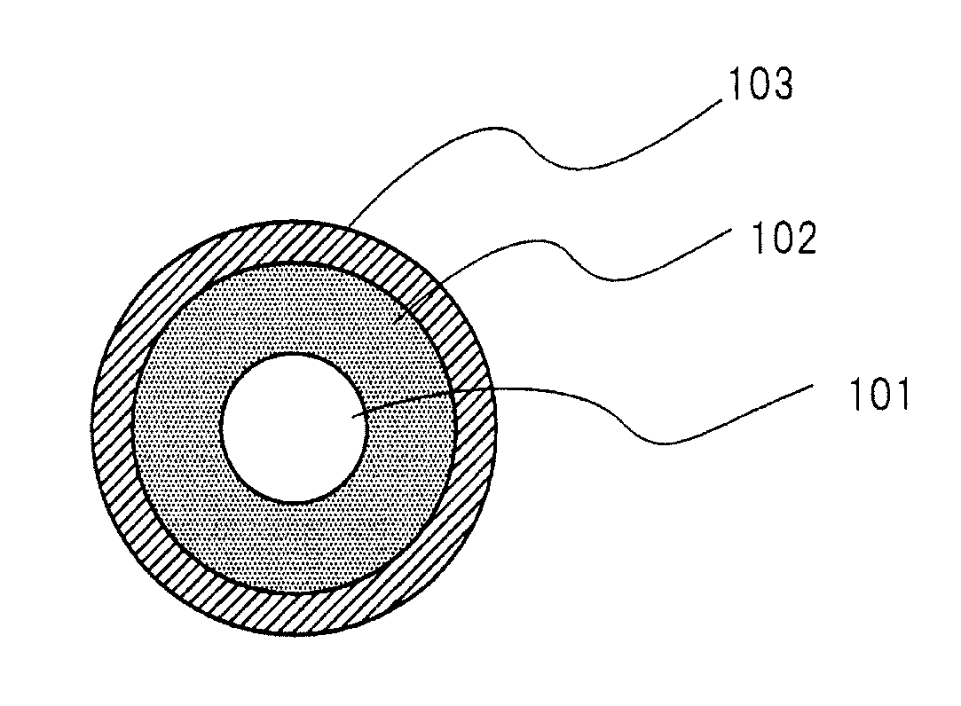
  • Charging member, process cartridge and electrophotographic apparatus
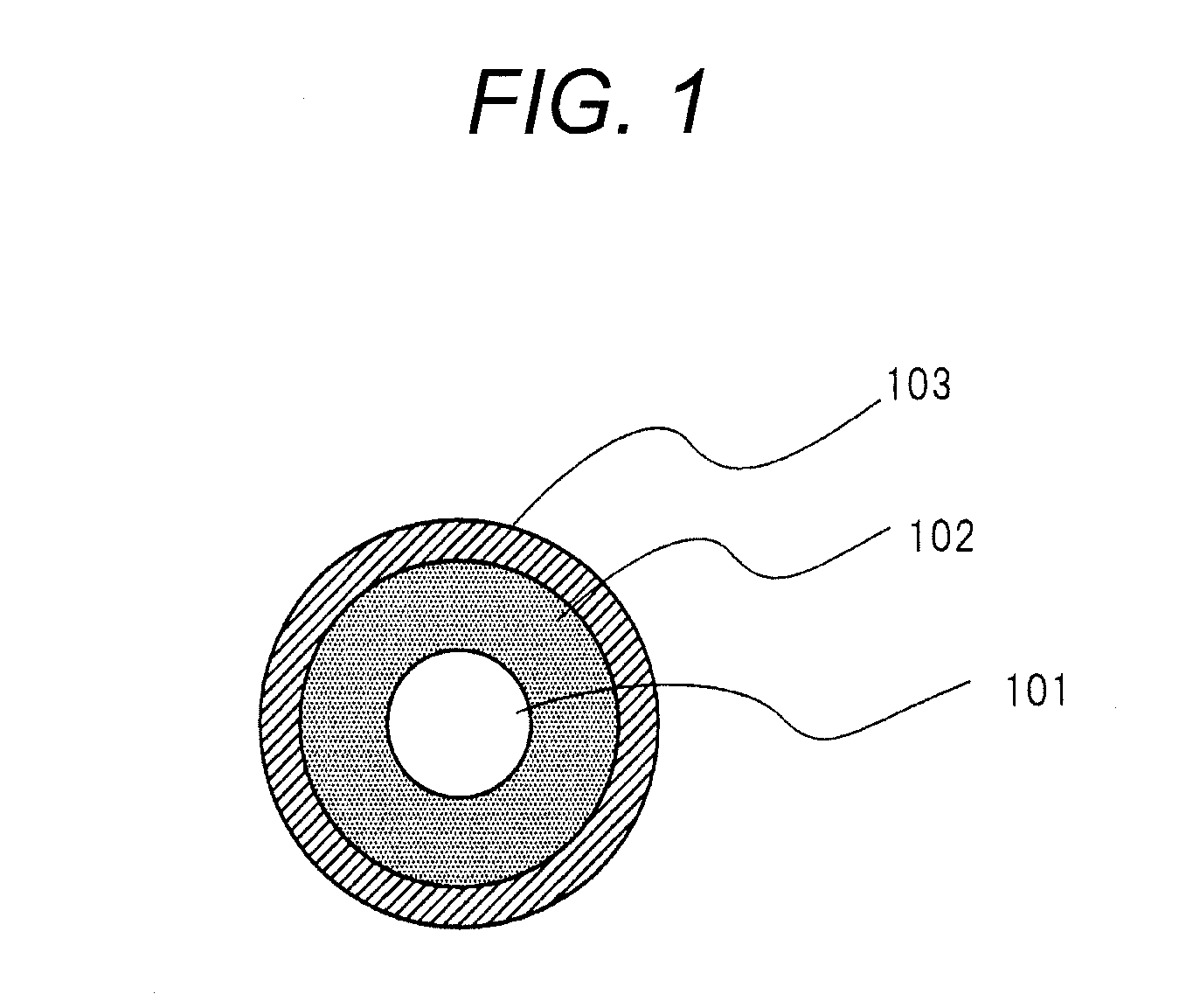
  • Charging member, process cartridge and electrophotographic apparatus
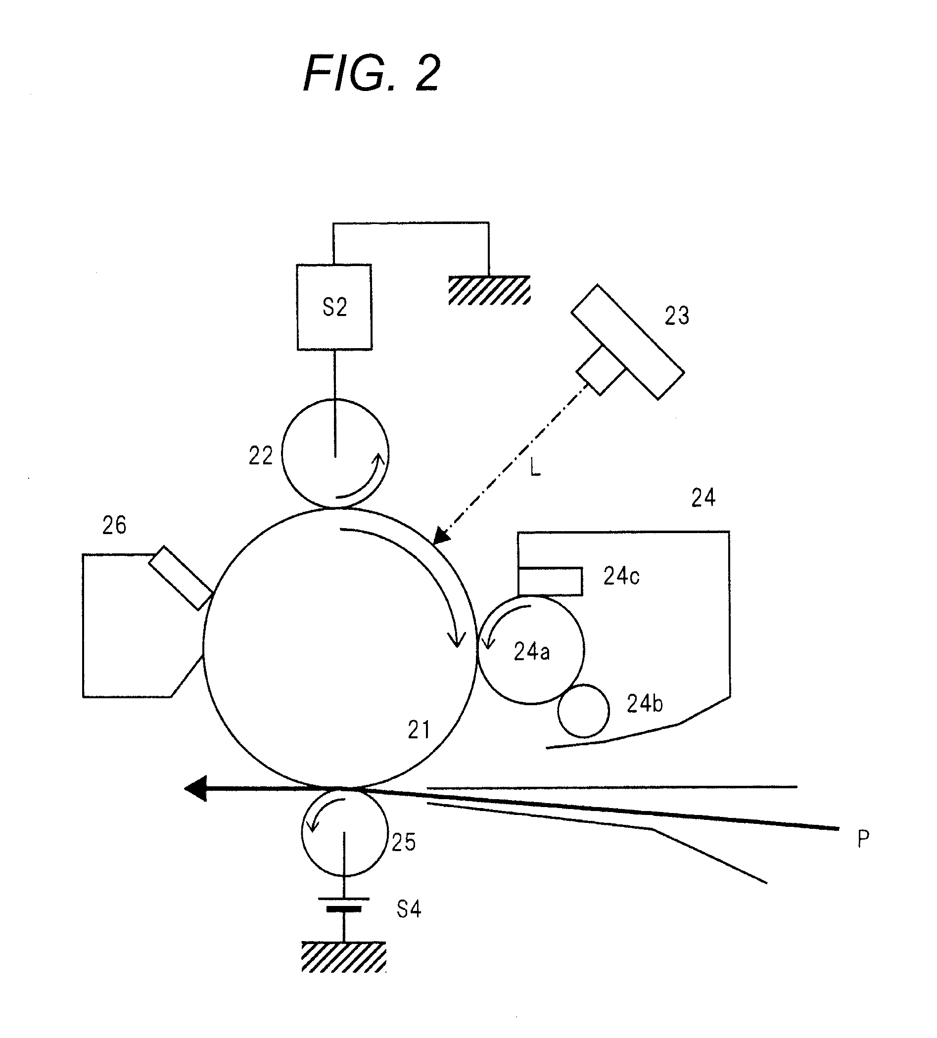
  • Charging member, process cartridge and electrophotographic apparatus

Examples


example 1

1. Preparation of Condensate 1-1

[0115]Then, a condensate for use in forming a surface layer was synthesized.

Synthesis-1

[0116]First, the following components shown in Table 2 were mixed, and then stirred at room temperature for 30 minutes.

TABLE 2Raw materialAmount usedGlycidoxypropylmethoxysilane (GPTMS, 42.3 g (0.179 mol)abbreviated as [EP-1], (hydrolyzable silanecompound), [trade name: KBM-403, producedby Shin-Etsu Chemical Co., Ltd.]Hexyltrimethoxysilane (HeTMS, abbreviated as224.8 g (1.087 mol)[He], (hydrolyzable silane compound), [tradename: KBM-3063, produced by Shin-EtsuChemical Co., Ltd.]Ion-exchange water 13.66 gEthanol [Kishida Chemical Co., Ltd.,355.26 gspecial grade]

[0117]Subsequently, the mixed components were heated to reflux using an oil bath at 120° C. for 20 hours, thereby providing condensate intermediate 1. Condensate intermediate 1 has a theoretical solid content (ratio of the mass of a polysiloxane polymerized product to the total mass of the solution, when all h...

example 2 to example 50

1. Preparation of Condensate Intermediates 2 to 9

[0139]Condensate intermediates 2 to 9 were prepared in the same manner as in condensate intermediate 1 except that the component (A) and the component (B) as well as the amounts used were changed as shown in Table 7. Herein, symbols such as “EP-1” in Table 7 represent compounds shown in Table 8, respectively.

TABLE 7CondensateAmount added / gMolar ratiointermediateComponent (A)Component (B)of water addedNo.EP-1EP-2EP-3EP-4HePhWater (E)EtOH(E) / {(A) + (B)}142.30———224.8—13.66355.260.602—35.99——235  14.28350.73——54.89—216.1—13.13351.884———43.72222.5—13.52356.28544.47————275.814.36301.42642.30———224.8—6.55358.660.307————32.74332.471.508————130.95234.266.009————163.68201.527.50

TABLE 8AbbreviationNameStructureManufacturerMWConcentrationEP-13-Glycidoxypropyltrimethoxy- silaneShin-Etsu Chemical Co., Ltd.236100%EP-24-(1,2-Epoxybutyl)trimethoxy- silaneCarbone Scientific192100%EP-38-Oxirane-2-yloctyltriethoxy- silaneSiKÉMIA319100%EP-41-(3,4- Epoxyc...


PUM


Abstract

The present invention provides a charging member that suppresses abnormal discharge which induces charging unevenness, and that has little contamination on a surface layer, to thereby enable uniform charging over a long period. The charging member includes a substrate, an elastic layer and a surface layer, wherein the surface layer contains a polymer compound having constitutional units represented by the following general formula (1), chemical formula (2) and general formula (3), and having a Si—O—Ti bond, a Ti—O-M bond and a Si—O-M bond. M is any atom selected from the group consisting of V, Nb and W.

Description

CROSS-REFERENCE TO RELATED APPLICATIONS[0001]This application is a continuation of International Application No. PCT / JP2013 / 003093, filed May 15, 2013, which claims the benefit of Japanese Patent Application No. 2012-116564, filed May 22, 2012.BACKGROUND OF THE INVENTIONField of the Invention[0002]The present invention relates to a charging member for use in contact charging of an electrophotographic apparatus, and a process cartridge and an electrophotographic apparatus.[0003]A charging member that abuts a photosensitive member to charge the photosensitive member is generally configured so as to have a rubber-containing elastic layer in order that an abutment nip between the photosensitive member and the charging member may be sufficiently and uniformly secured. Since such an elastic layer ineluctably contains a low-molecular weight component, the low-molecular weight component may bleed toward the surface of the charging member due to long-term use of the charging member to contam...

Claims


Application Information

Patent Timeline
Patent Type & Authority Applications(United States)
IPC IPC(8): B05C1/08G03G15/02
CPCG03G15/0233
Inventor KURACHI, MASAHIROKODAMA, MASATAKADOI, NORIYUKISUZUMURA, NORIKOMASU, HIROKIKURODA, NORIAKI
Owner CANON KK
Learn More