
Apparatus for producing single crystal silicon

a technology of apparatus and silicon, applied in the direction of crystal growth process, polycrystalline material growth, protective fluid, etc., can solve the problems of generating contamination from the sealing member, contaminating the support member, and deteriorating sealing properties, and achieve high-quality single crystal silicon

Active Publication Date: 2012-11-20
HIGH-PURITY SILICON CORP
View PDF9 Cites 0 Cited by
  • Summary
  • Abstract
  • Description
  • Claims
  • Application Information

AI Technical Summary

Benefits of technology

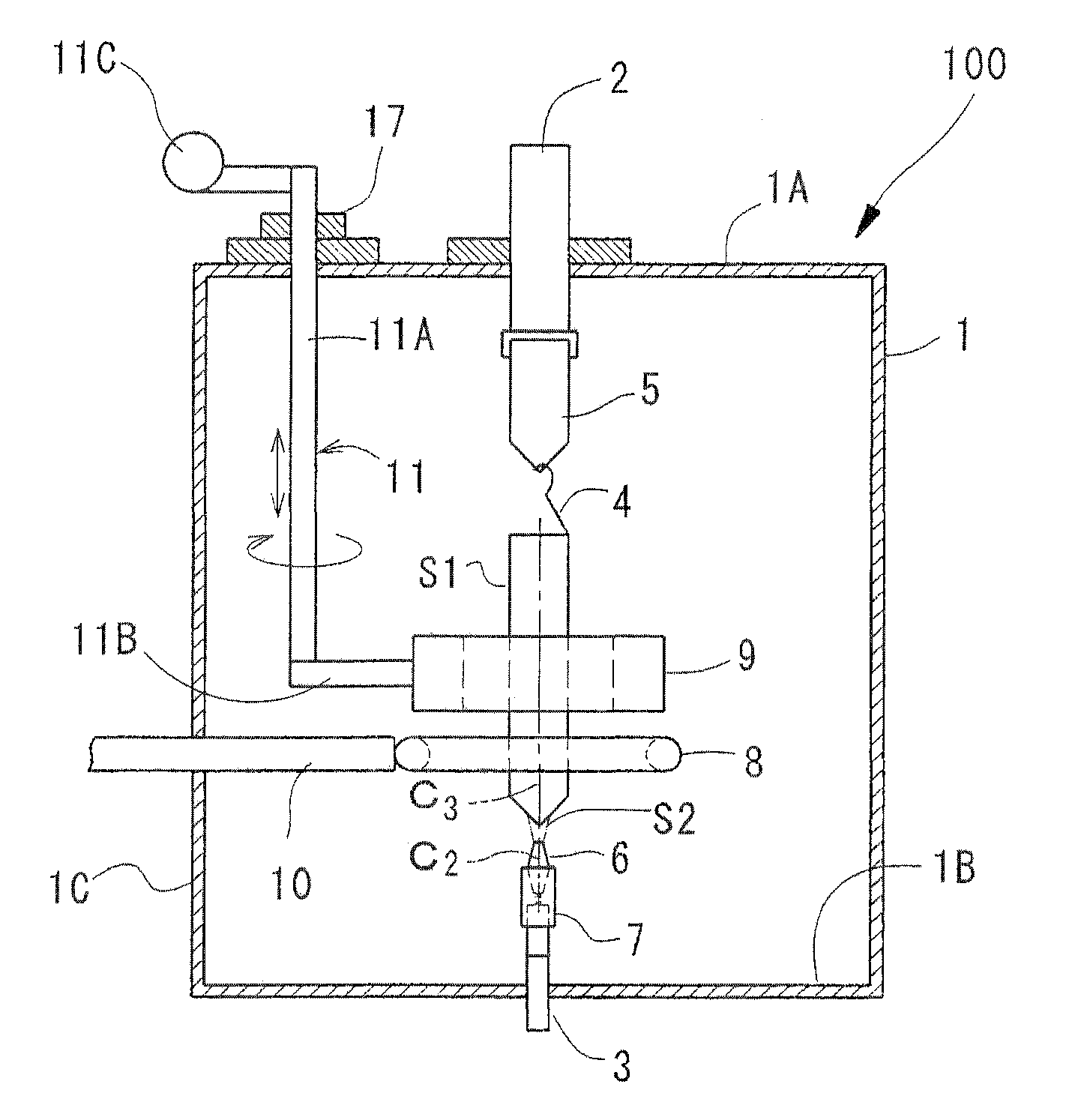
[0012]In other words, a design is provided in which the conductive member of the exothermic ring is covered with the quartz-coated member, and the cooling medium flows inside the support member which is holding the ring. As a result, when the exothermic ring is subjected to induction heating by the induction heating coil, that heat is cooled by the cooling medium inside the support member, making it possible to produce a high quality single crystal silicon with extremely little contamination.
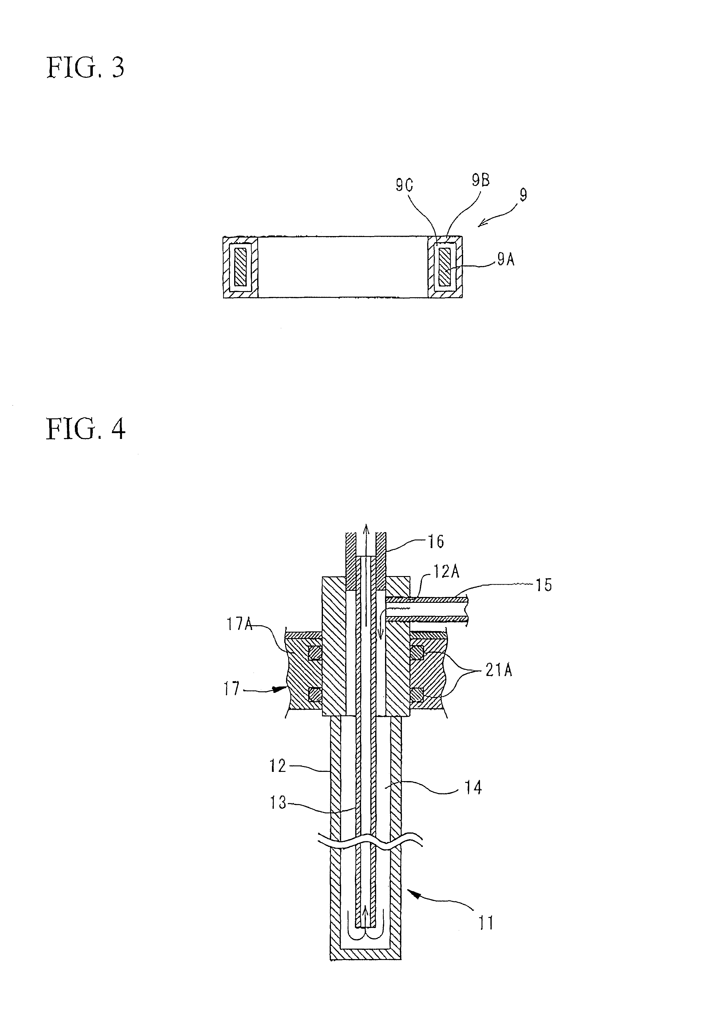
[0015]In addition, a space may be formed in between the conductive member and the quartz-coated member, with this space then evacuated to create a vacuum state. By forming this internal space, it is possible to prevent heat stress between the conductive member and the quartz-coated member. In addition, by providing a vacuum state within this internal space and deterioration of the conductive member is prevented.
[0017]In the present invention's apparatus for producing single crystal silicon, the conductive member of the exothermic ring is covered with the quartz-coated member, and the cooling medium flows inside the support member that holds the exothermic ring As a result, the heat from the exothermic ring is cooled by the cooling medium inside the support member. Thus, contamination from the exothermic ring, the support member, and the sealing member between the support member and the housing, can be prevented. As a result, it is possible to produce a high quality single crystal silicon.

Problems solved by technology

As a result, this can lead to contamination from the support member.
In addition, heat is transmitted to the sealing member in between the support member and the housing, causing the sealing properties to deteriorate and generating contamination from the sealing member.
Moreover, a further problem is the deterioration in the quality of the single crystal silicon which results when the environment degrades due to mixing in of external gases when the sealing properties deteriorate.

Method used


Image

  • Apparatus for producing single crystal silicon
  • Apparatus for producing single crystal silicon
  • Apparatus for producing single crystal silicon

Examples


Embodiment Construction

Preferred Embodiments of the Present Invention

[0026]Preferred embodiments of the apparatus for producing single crystal silicon according to the present invention will now be explained with reference to the accompanying figures.

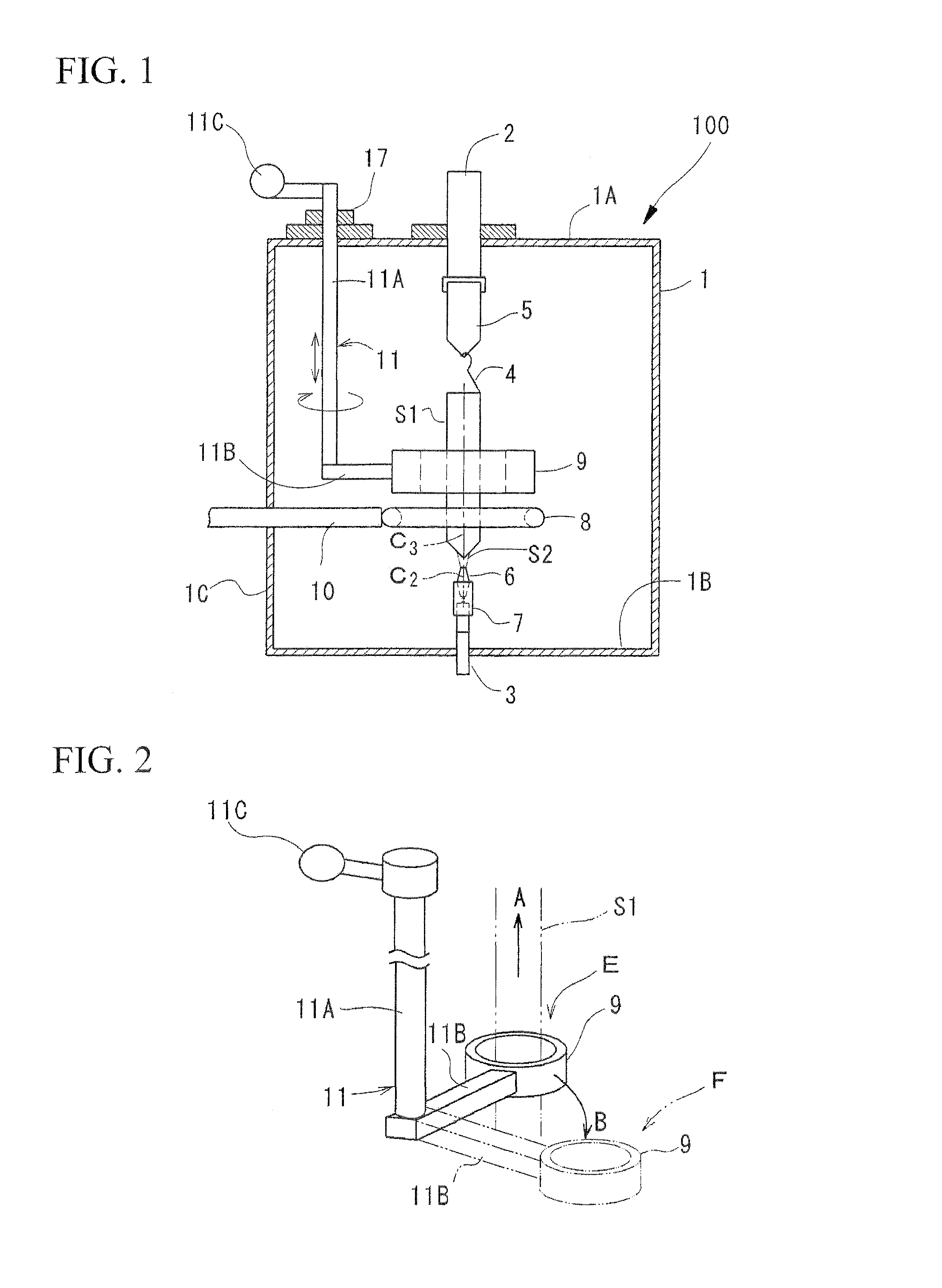
[0027]FIG. 1 is a schematic structural view of an apparatus for producing single crystal silicon 100 according to the first embodiment. In the figure, numeric symbol 1 indicates a housing which is filled with an inert gas (argon gas). An upper drive shaft 2 is provided in the center of the top wall 1A of this housing for rotational driving and reciprocated driving in the vertical direction. In addition, a lower drive shaft 3 is provided to the bottom 1B of the housing 1 opposite the upper drive shaft 2 and so as to be on the same axis, for rotational driving and reciprocated driving in the vertical direction. A polycrystal holder 5 for holding the polycrystalline silicon rod S1 which is the sample material via a hoist 4 consisting of molybdenum wire is provid...


PUM


Abstract

An apparatus for producing single crystal silicon comprising: an induction heating coil that is disposed around the polycrystalline silicon rod for fusing the polycrystalline silicon rod; an exothermic ring that has a quartz-coated member covering the conductive member; a support member that supports the exothermic ring and passes through a wall of the housing in a rotatable manner; an operating device that rotates the support member and reciprocates the exothermic ring between a heating position where the exothermic ring is positioned close to the induction heating coil and a stand-by position where the exothermic ring is receded from the heating position; a sealing member that is provided between the wall of the housing and the support member and maintains the hermitic therebetween; and a cooling flow path that is formed in the support member and flows a cooling medium.

Description

BACKGROUND OF THE INVENTION[0001]1. Field of the Invention[0002]The present invention relates to an apparatus for producing single crystal silicon, and specifically, to an apparatus for producing single crystal silicon in which the single crystal is grown using the FZ method.[0003]Priority is claimed on Japanese Patent Application No. 2007-331548, filed Dec. 25, 2007, the content of which is incorporated herein by reference.[0004]2. Description of Related Art[0005]The apparatus disclosed in Japanese Patent Application, First Publication No. Hei 7-10681 is a conventionally known example of an apparatus for producing single crystal silicon in which this type of FZ (float zone) method is employed. This apparatus for producing single crystal silicon is provided with a housing which has an inert gas environment internally; a polycrystal holder that is installed to an upper drive shaft (positioning rod) inside the housing, and which holds at its bottom end the polycrystalline silicon rod ...

Claims


Application Information

Patent Timeline
IPC IPC(8): C30B35/00C30B15/00C30B30/04C30B27/02C30B28/10C30B11/00C30B21/06
CPCC30B13/00C30B13/20C30B13/32C30B29/06Y10T117/1032Y10T117/1024Y10T117/1064Y10T117/1016Y10T117/10
Inventor CHIKUSA, NOBORUKITAGAWA, TERUHISAITO, MASAKIITO, TAKANORI
Owner HIGH-PURITY SILICON CORP
Learn More