Method for selectively modulating neural elements in the dorsal horn

a neural element and dorsal horn technology, applied in the field of tissue stimulation systems, can solve the problems of requiring the neuromodulator device to be charged more, consuming an excessive amount of electrical energy, and having to suffer adversity,

Active Publication Date: 2014-03-20
BOSTON SCI NEUROMODULATION CORP
View PDF3 Cites 113 Cited by
  • Summary
  • Abstract
  • Description
  • Claims
  • Application Information

AI Technical Summary

Benefits of technology

[0009]In accordance with one aspect of the present inventions, a method of providing therapy to a patient comprises conveying pulsed electrical current at a defined pulse width and a defined pulse rate into spinal cord tissue of the patient. The defined pulse width is equal to or less than 200 μs, and the defined pulse rate is less than 1500 Hz, such that neural elements (e.g., nerve endings) in the dorsal horn are modulated. In one method, the neural elements in the dorsal horn are preferentially stimulated over dorsal column fibers. The conveyance of the pulsed electrical current may stimulate neural elements of the dorsal horn by evoking action potentials in the neural elements, or may be subthreshold and not evoke action potentials in the neural elements. In one method, the defined pulse width is within the range of 10 μs-100 μs, and preferably in the range of 10 μs-50 μs. The pulsed electrical current may be anodic or cathodic. The pulsed electrical current may be conveyed into the spinal cord tissue without causing a perception of paresthesia in t

Problems solved by technology

Although alternative or artifactual sensations are usually tolerated relative to the sensation of pain, patients sometimes report these sensations to be uncomfortable, and therefore, they can be considered an adver

Method used


Image

  • Method for selectively modulating neural elements in the dorsal horn
  • Method for selectively modulating neural elements in the dorsal horn
  • Method for selectively modulating neural elements in the dorsal horn

Examples


Embodiment Construction

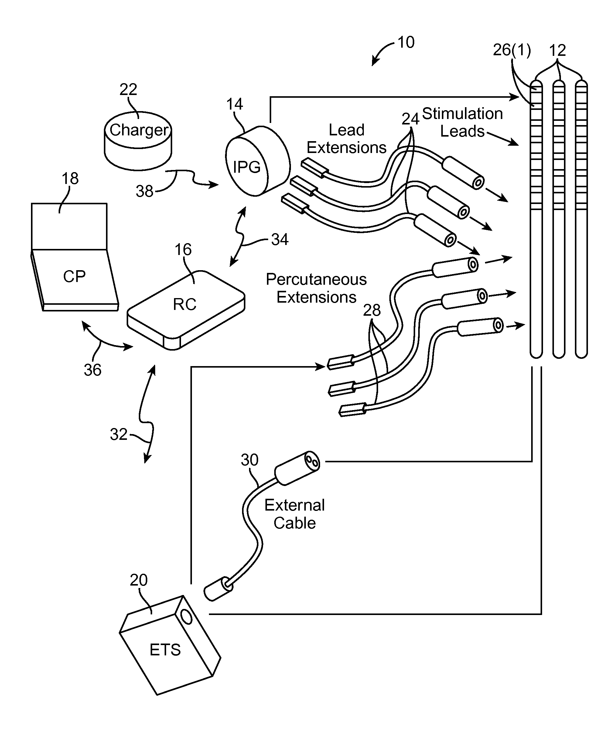
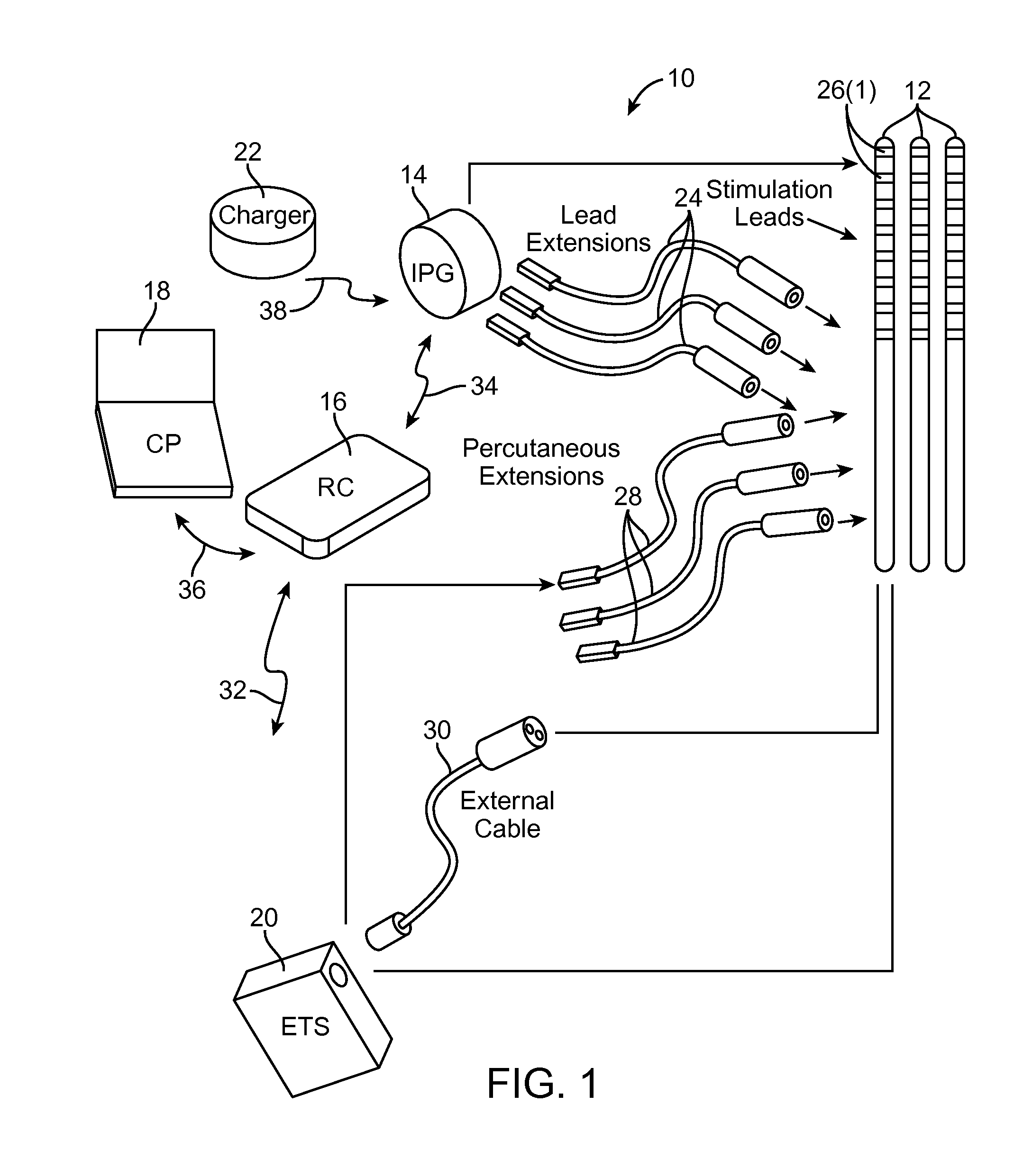
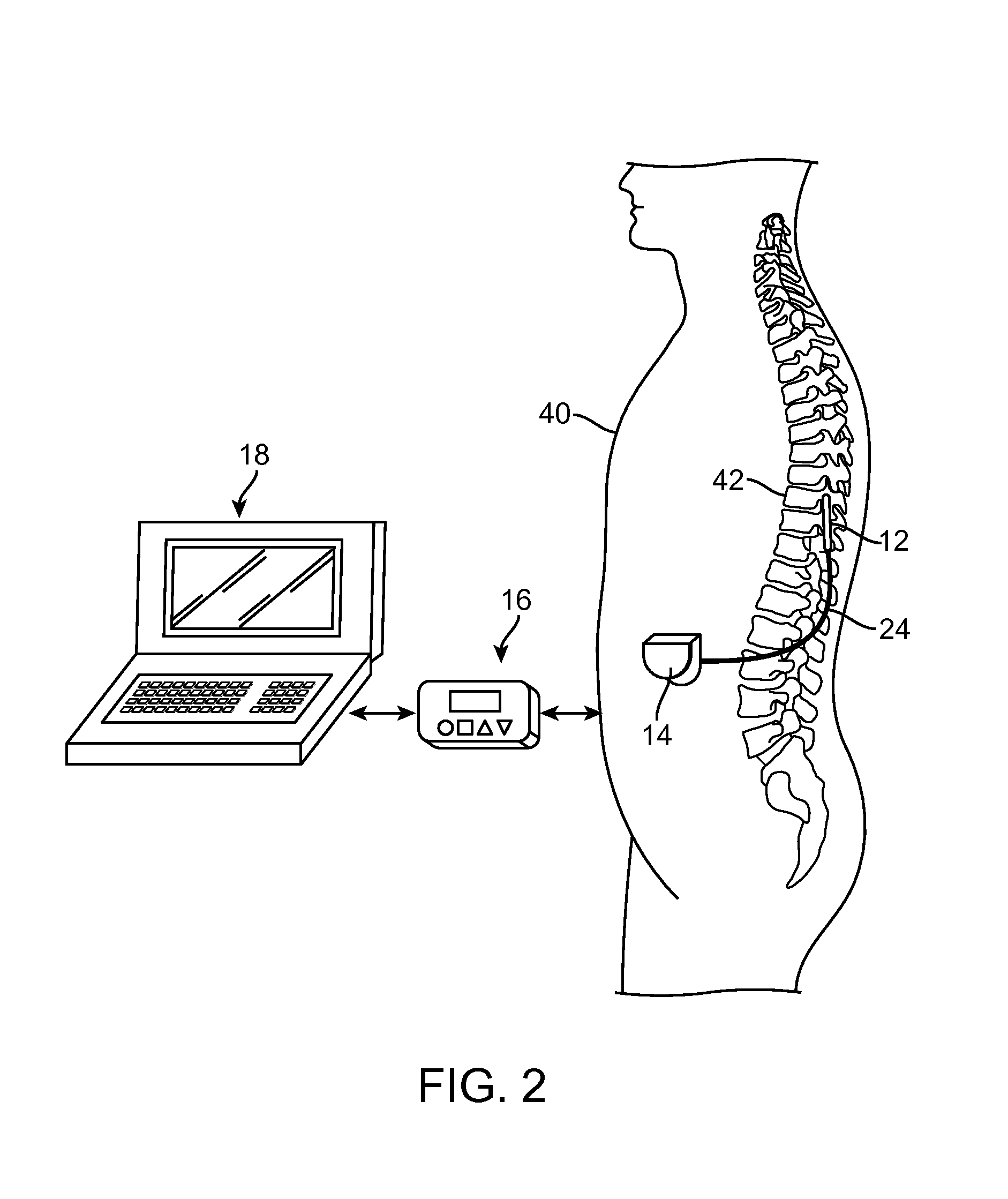
[0020]Turning first to FIG. 1, an exemplary spinal cord modulation (SCM) system 10 generally comprises a plurality of modulation leads 12 (in this case, three), an implantable pulse generator (IPG) 14 (or alternatively RF receiver-stimulator), an external remote control RC 16, a Clinician's Programmer (CP) 18, an External Trial Modulator (ETM) 20, and an external charger 22.

[0021]The IPG 14 is physically connected via one or more lead extensions 24 to the modulation leads 12, which carry a plurality of electrodes 26 arranged in an array. The modulation leads 12 are illustrated as percutaneous leads in FIG. 1, although as will be described in further detail below, a surgical paddle lead can be used in place of the percutaneous leads. As will also be described in further detail below, the IPG 14 includes pulse generation circuitry that delivers electrical modulation energy in the form of a pulsed electrical waveform (i.e., a temporal series of electrical pulses) to the electrode array...


PUM


Abstract

A method of providing therapy to a patient. The method comprises conveying pulsed electrical current at a defined pulse width and a defined pulse rate into spinal cord tissue. The defined pulse width is equal to or less than 200 μs, and the defined pulse rate is less than 1500 Hz, such that neural elements in the dorsal horn are modulated and/or the patient does not perceive paresthesia during the conveyance of the pulsed electrical current into the spinal cord tissue.

Description

RELATED APPLICATION DATA[0001]The present application claims the benefit under 35 U.S.C. §119 to U.S. provisional patent application Ser. No. 61 / 703,195, filed Sep. 19, 2012. The foregoing application is hereby incorporated by reference into the present application in its entirety.FIELD OF THE INVENTION[0002]The present invention relates to tissue stimulation systems, and more particularly, to a system and method for stimulating spinal nerve tissue to provide therapy to a patient.BACKGROUND OF THE INVENTION[0003]Implantable neurostimulation systems have proven therapeutic in a wide variety of diseases and disorders. For example, Spinal Cord Stimulation (SCS) techniques, which directly stimulate the spinal cord tissue of the patient, have long been accepted as a therapeutic modality for the treatment of chronic neuropathic pain syndromes, and the application of spinal cord stimulation has expanded to include additional applications, such as angina pectoralis, peripheral vascular dise...

Claims


Application Information

Patent Timeline
IPC IPC(8): A61N1/36
CPCA61N1/36071A61N1/0551A61N1/0553A61N1/36171A61N1/36175
Inventor LEE, DONGCHULDOAN, QUE T.
Owner BOSTON SCI NEUROMODULATION CORP
Why Eureka
Try Eureka