Precision forged cartridge case

Active Publication Date: 2014-03-27
THE NAT MASCH CO
View PDF9 Cites 19 Cited by
  • Summary
  • Abstract
  • Description
  • Claims
  • Application Information

AI Technical Summary

Benefits of technology

[0004]The invention provides an improved cartridge case, as well as a method and apparatus for its manufacture. The case is fully cold formed from metal wire stock, typically brass, in a single forming machine. The disclosed case is of the rimless, solid head type with an ejector groove on the head end. The case is formed at high production speeds to finished shape with stock removal limited to cutting a short ring off the forward end of a deep

Problems solved by technology

The strip stock method produces a high scrap ratio, requires energy for annealing, is slow, and occupies considerably floor space.
There are several additional drawbacks to these known methods of manufacturing cartridge cases.
Transferring case preforms from one bank of forming machines, for example, to a bank of turning machines, introduces dimensional variations that can be difficult to manage because of the

Method used


Image

  • Precision forged cartridge case
  • Precision forged cartridge case
  • Precision forged cartridge case

Examples


Example

[0013]While the disclosed solid head cartridge case is sometimes referred to as “rimless”, it will be understood that this term applies to belted cases with their heads slightly larger than forward areas of their bodies. Despite the industry “rimless” terminology, the radially outer part of the cartridge case head at the back of the ejector groove can be considered a rim.

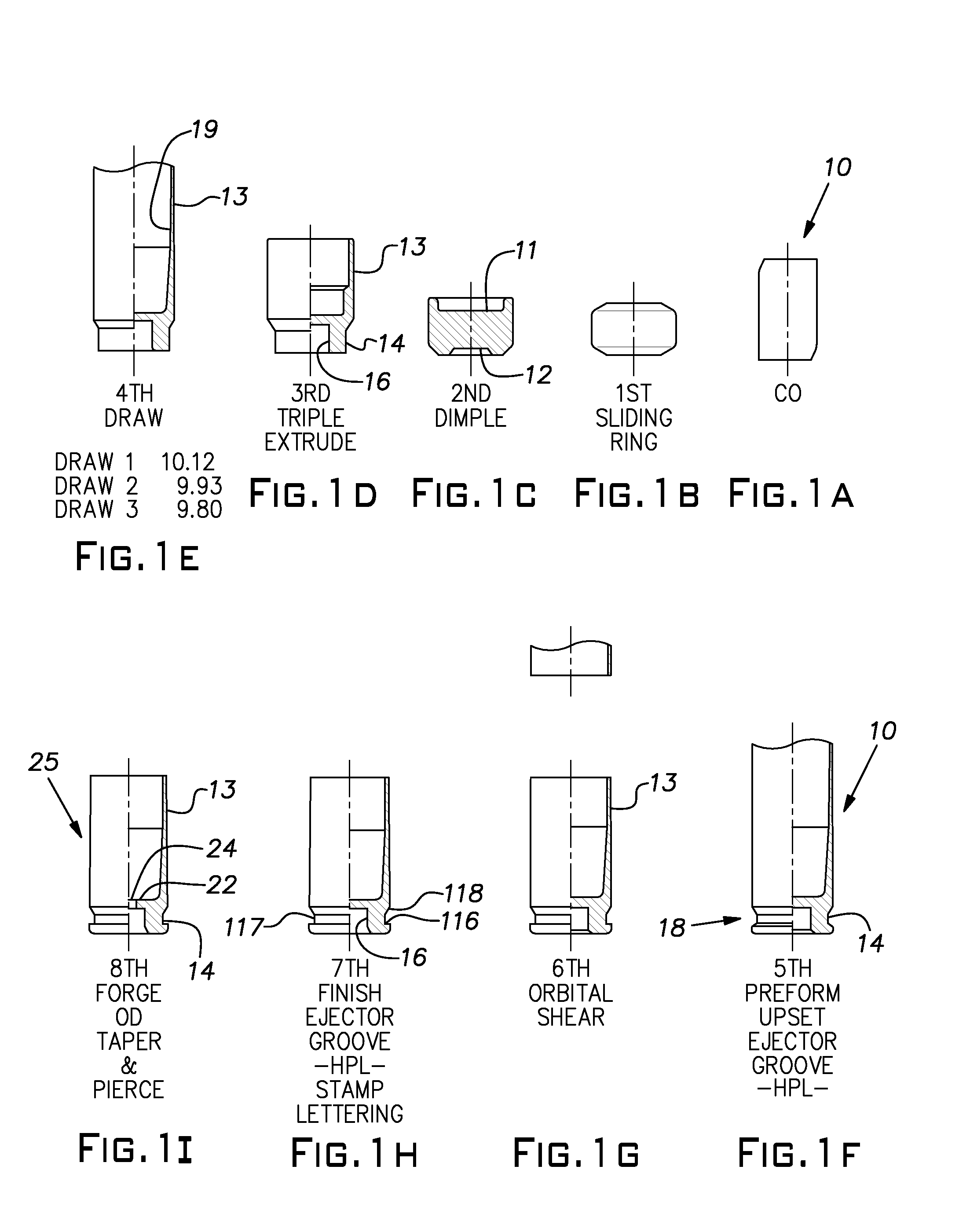
[0014]Referring to FIGS. 1A-1I, there is illustrated a preferred sequence of forming a finished cartridge case starting with solid wire stock in a progressive forming or forging machine. A blank 10, shown in FIG. 1A, is cut from coiled round wire stock with a shear operating synchronously with other operations of a forging machine described below in greater detail. A conventional transfer device, having an axial movement component, not shown, operates to shift a blank 10 from one station to the next, i.e. from right to left in FIGS. 1A-1I. At a first forming station (FIG. 1B), the blank 10, transferred from the cut-...


PUM

PropertyMeasurementUnit
Lengthaaaaaaaaaa
Diameteraaaaaaaaaa
Electrical resistanceaaaaaaaaaa

Abstract

An improved cartridge case completely produced net shape on a progressive cold former that includes a trim to lengthy station with an internal shearing tool.

Description

BACKGROUND OF THE INVENTION[0001]The invention relates to cartridge cases and their manufacture.PRIOR ART[0002]Brass cases for firearm cartridges are conventionally made in numerous steps and on successive machines, often with intermediate annealing steps. Traditionally, cases are formed from strip stock that is cupped and then drawn. Once drawn, the blanks are machined to length and to provide an ejector groove. The strip stock method produces a high scrap ratio, requires energy for annealing, is slow, and occupies considerably floor space. It is known to cold form a hollow thin wall intermediate blank for a cartridge case from solid wire. Whether made from strip stock or wire stock, when a heavily drawn preform is produced, it has an irregular edge on the open end which, traditionally, is machined for a precise end surface after discharge from the forming tooling. The preform, after discharge from the forming tooling, is also typically machined to create an ejector groove adjacent...

Claims


Application Information

Patent Timeline
IPC IPC(8): F42B33/00B21D31/02F42B5/28B21D51/54B21D35/00B21D37/10B21D37/08
CPCB21D51/54B23D21/14F42B5/28B21J13/02B21J5/025B23P15/22B21J5/027B21K21/04
Inventor HAY, THOMAS E.CARPER, JEFFREY W.WASSERMAN, STANLEY J.
Owner THE NAT MASCH CO
Why Eureka
Try Eureka