Electrical apparatus having a gas insulation containing a fluorinated compound
a technology of fluorinated compound and electric apparatus, which is applied in the direction of fluid loss/gain rate measurement, fluid tightness measurement, instruments, etc., can solve the problems of increasing the gas pressure in the housing, and achieve the effect of improving the effectiveness of the means, increasing the gas pressure, and limiting the loss of heat produced by the heating means
- Summary
- Abstract
- Description
- Claims
- Application Information
AI Technical Summary
Benefits of technology
Problems solved by technology
Method used
Image
Examples
first embodiment
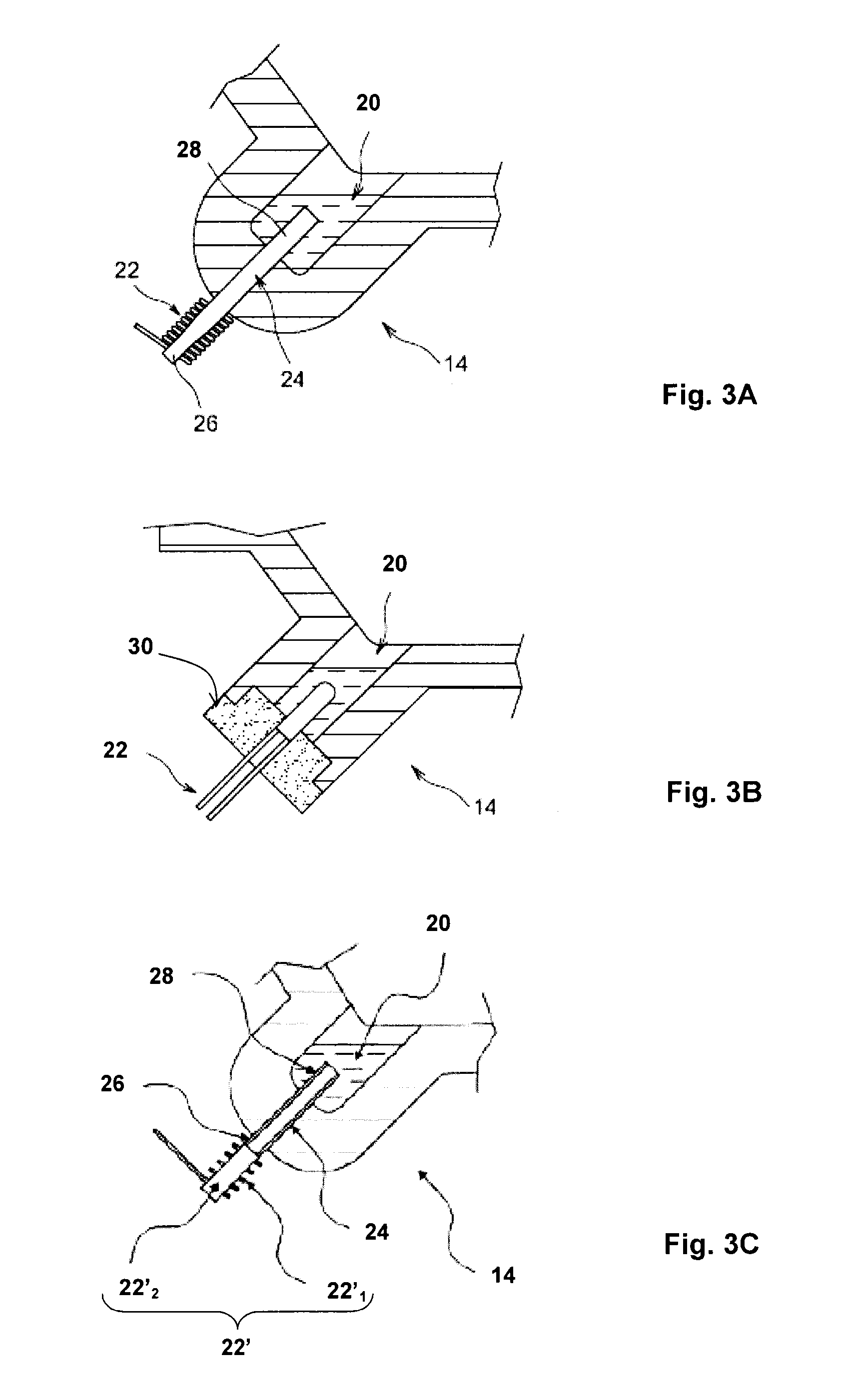
[0032]In a first embodiment illustrated in FIG. 3A, the heating means contain a resistor 22, for example an electrical resistor, which produces heat that is transmitted to the condensate; the heat produced by the resistor 22 is transmitted to the condensate by way of a heat conductor 24. This transmission of heat is particularly advantageous in the case where the housing 12 is made of thermally insulating material, because only the heat conductor 24 allows the heat produced by the resistor 22 to reach the condensate 20. It will nonetheless be understood that the heat conductor 24 may also be used for the embodiment in which the housing 12 is made from a thermally conductive material.
[0033]The resistor 22 is thus arranged outside the tank 14, preferably outside the housing 12, and the heat conductor 24 passes through the wall of the tank 14. A first end 26 of the heat conductor is located outside the housing 12 and is heated by the resistor, and a second end 28 of the heat conductor ...
second embodiment
[0036]In a second embodiment shown in FIG. 3C, the heating means 22′ comprise a solenoid 22′1 and its core 22′2. The heat produced is transmitted to the condensate 20, preferably by a way of a heat conductor 24, which may also be a filling tube: the solenoid 22′1 and its core 22′2 are thus arranged outside the tank 14, outside the housing 12, and the heat conductor 24 passes through the wall of the tank 14, a first end 26 of the heat conductor 24 being located outside the housing 12 and heated by the means 22′, and the second end 28 located inside the tank 14 heating the condensate 20. Thus, the heat produced by the solenoid and its core is transmitted to the condensate 20 by way of the heat conductor 24.
[0037]In another embodiment illustrated in FIG. 5, the tank 14 of condensate 20 contains a lower bottom wall 32 in which a cavity 34 is made. The cavity 34 protrudes vertically upwards with respect to the bottom wall 32: it therefore extends into the inside of the tank 14. The cavit...
PUM
 Abstract
Description
Claims
Application Information
 - R&D
- Intellectual Property
- Life Sciences
- Materials
- Tech Scout
- Unparalleled Data Quality
- Higher Quality Content
- 60% Fewer Hallucinations
Browse by: Latest US Patents, China's latest patents, Technical Efficacy Thesaurus, Application Domain, Technology Topic, Popular Technical Reports.
© 2025 PatSnap. All rights reserved.Legal|Privacy policy|Modern Slavery Act Transparency Statement|Sitemap|About US| Contact US: help@patsnap.com


