Rotating Electric Machine and Method of Manufacturing Same

a technology of rotating electric machines and electric motors, applied in the direction of dynamo-electric machines, windings insulation materials, solid insulation, etc., can solve the problems of increasing the vibration applied to the stator core and heat generation of the rotating electric machine, the coating on enameled wires is peeled off, and the adhesion force between the slots in the stator core and the stator coil becomes insufficien

Active Publication Date: 2014-03-27
HITACHI ASTEMO LTD
View PDF4 Cites 13 Cited by
  • Summary
  • Abstract
  • Description
  • Claims
  • Application Information

AI Technical Summary

Benefits of technology

[0013]According to the invention, a rotating electric machine having both...

Problems solved by technology

Recent rotating electric machines suffer from increasing vibration applied to stator coils and heat generation by the stator coils due to higher power.
This creates, however, another problem that coating on enameled wires is peeled off due to thermal expansion and thermal shrinkage of the varnish associated with heat ...

Method used


Image

  • Rotating Electric Machine and Method of Manufacturing Same
  • Rotating Electric Machine and Method of Manufacturing Same
  • Rotating Electric Machine and Method of Manufacturing Same

Examples


Embodiment Construction

[0029]An embodiment of the invention will be described below with reference to the drawings.

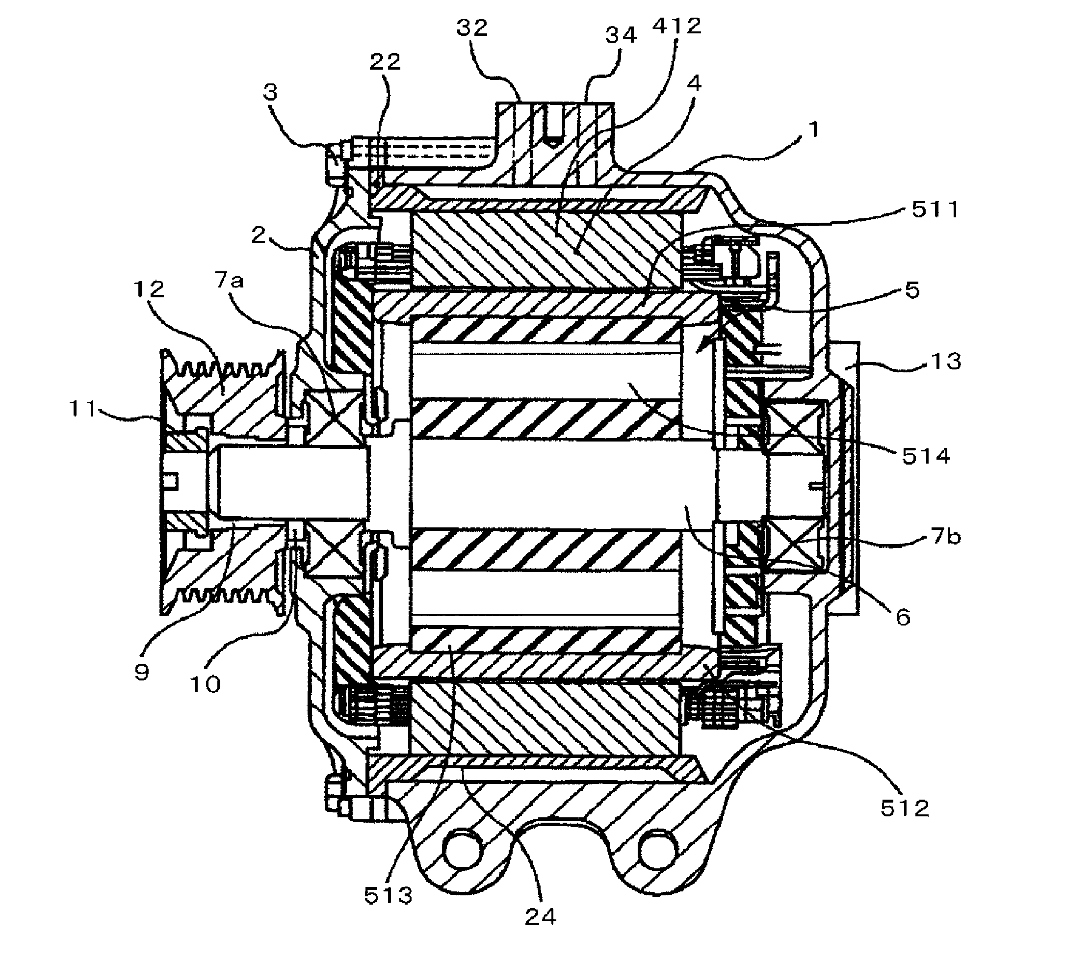
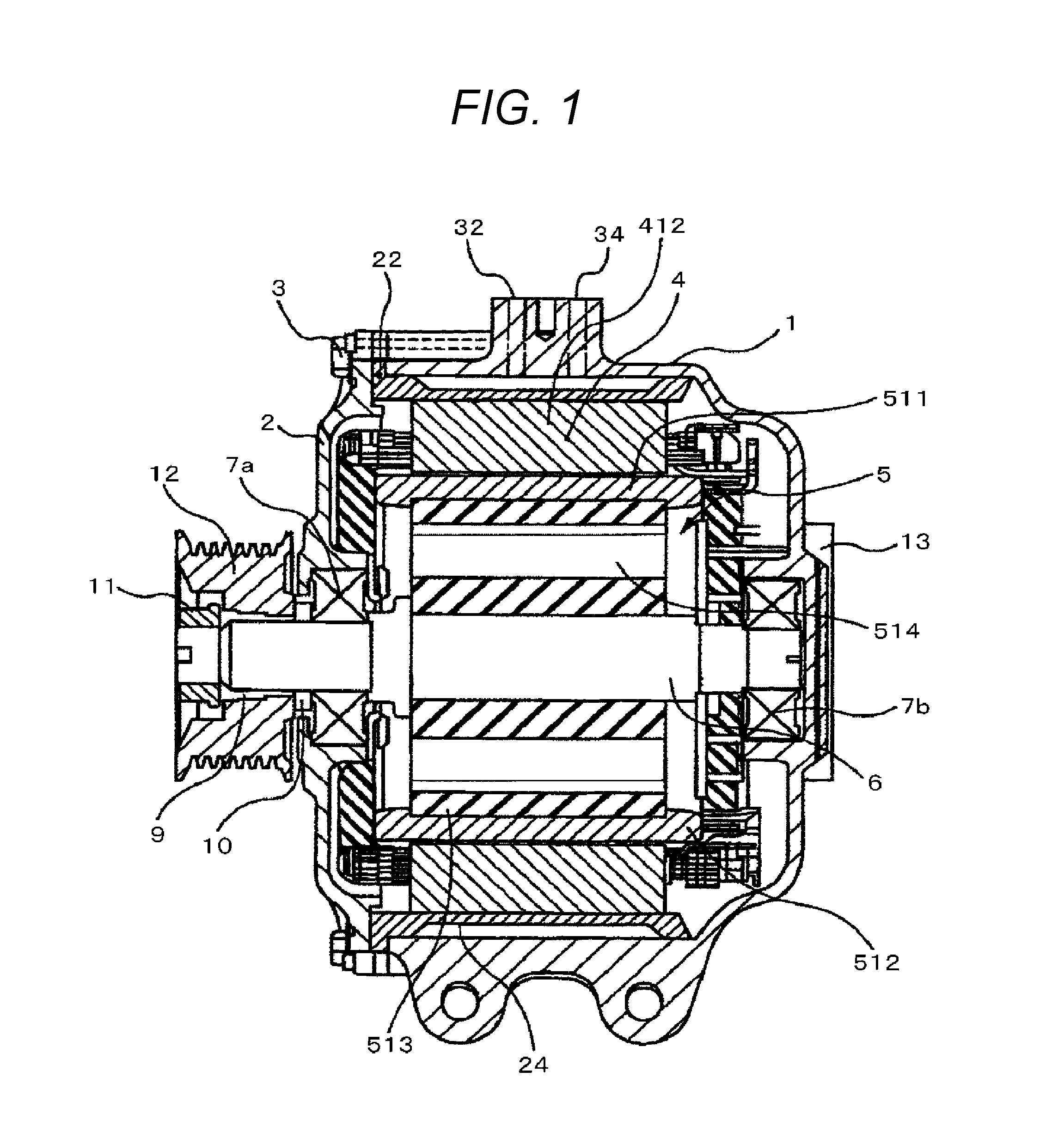
[0030]FIG. 1 is a sectional side view of an induction motor according to a first embodiment. A squirrel cage induction motor that is an example of a rotating electric machine includes a housing having a cylindrical shape with one end in the axial direction being open and a bottom being closed, and a cover 2 for searing the open end of the housing 1. The housing 1 and the cover 2 are fastened together with multiple, such as six, bolts 3. The housing 1 is provided therein with a water channel member 22 to which a stator 4 is fixed inside thereof by shrink fit or in other manners. A flange at the left end of the water channel member 22 in FIG. 1 is fixed between the housing 1 and the cover 2, and a water channel 24 is formed between the water channel member 22 and the housing 1. Coolant for cooling the rotating electric machine is introduced into the water channel through an inlet 32 formed in t...


PUM

PropertyMeasurementUnit
Temperatureaaaaaaaaaa
Glass transition temperatureaaaaaaaaaa

Abstract

A rotating electric machine includes: a stator including a stator core, slots provided in the stator core at equal intervals along the circumferential direction, and coils placed in the stator slots and configured to generate a rotating magnetic field; and a rotor rotatably provided with a predetermined rotation gap between the stator core and the rotor, wherein the rotating electric machine further comprising a first varnish applied between the slots in the stator core and the coils for impregnation, and a second varnish applied directly onto enamel coating of the coils outside of the slots in the axial direction, the first varnish is a thermosetting varnish having a shear bond strength of a flat wire between the coils and the varnish is higher than that of the second varnish, and the second varnish is a thermosetting varnish having a glass transition temperature of approximately 104° C. or lower and the glass transition temperature of the second varnish by the DMA method is lower than that of the first varnish.

Description

TECHNICAL FIELD[0001]The present invention relates to a rotating electric machine and a method of manufacturing the same.BACKGROUND ART[0002]Recent rotating electric machines suffer from increasing vibration applied to stator coils and heat generation by the stator coils due to higher power.[0003]To suppress vibration of the stator coils in slots in a stator core, it is known to apply varnish (such as epoxy varnish) having a high strength (including a high bond strength and a high heat resistance) between the stator core and the stator coils for impregnation and adhesion. This creates, however, another problem that coating on enameled wires is peeled off due to thermal expansion and thermal shrinkage of the varnish associated with heat cycles and heat shock at coil ends outside of the stator core.[0004]Thus, if a flexible unsaturated polyester varnish having a lower bond strength is used, peel off of the enamel coating can be prevented. However, the adhesion force between the slots ...

Claims


Application Information

Patent Timeline
IPC IPC(8): H02K3/30H02K15/02
CPCH02K15/02H02K3/30H02K3/34H02K3/38H02K15/12Y10T29/49012
Inventor KURAHARA, YOSHIMIOBATA, KOJIHAGIWARA, SHUYA
Owner HITACHI ASTEMO LTD
Why Eureka
Try Eureka