
Surface property inspection device and surface property inspection method

a technology of surface property and inspection device, which is applied in the direction of electrical/magnetic thickness measurement, instruments, material magnetic variables, etc., can solve the problems of unusability of tested products, not all products can therefore be directly tested, etc., and achieve the effect of improving detection accuracy

Active Publication Date: 2014-03-27
SINTOKOGIO LTD
View PDF0 Cites 25 Cited by
  • Summary
  • Abstract
  • Description
  • Claims
  • Application Information

AI Technical Summary

Benefits of technology

The invention allows for a quick and accurate inspection of surface treatment conditions using a simple circuit configuration. This is achieved by comparing the output signal of a sample with a benchmark sample using a judgment device that can pass or fail the surface treatment condition. The AC bridge circuit configuration eliminates the need for temperature correction, calibration, and redesign of the circuit for changes in impedance. Additionally, the invention ensures that pressure loads are equal for each sample, resulting in improved detection accuracy.

Problems solved by technology

This led to the problem that not all products could therefore not be directly tested, and because testing was destructive, tested products became unusable.

Method used


Image

  • Surface property inspection device and surface property inspection method
  • Surface property inspection device and surface property inspection method
  • Surface property inspection device and surface property inspection method

Examples


Embodiment Construction

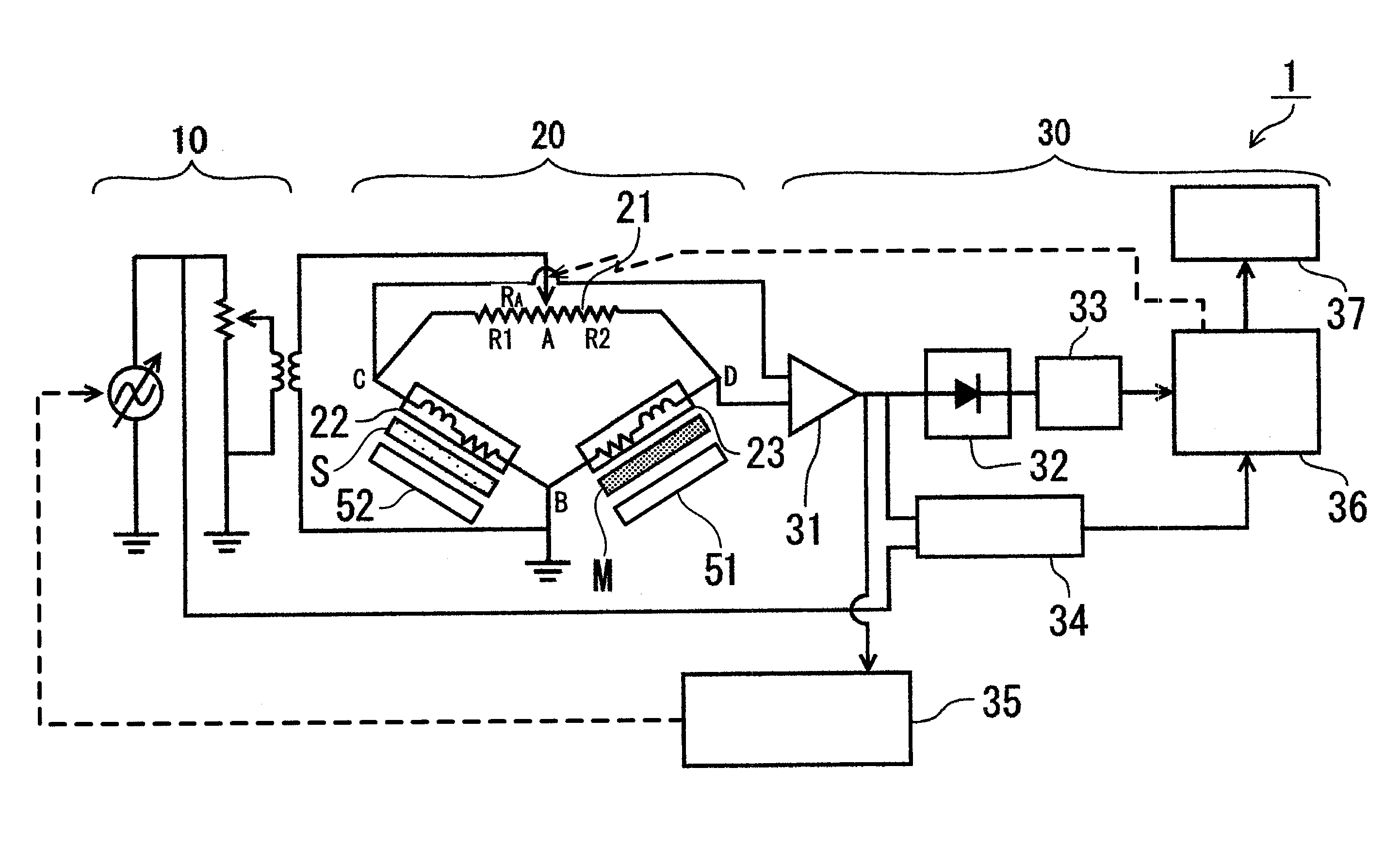
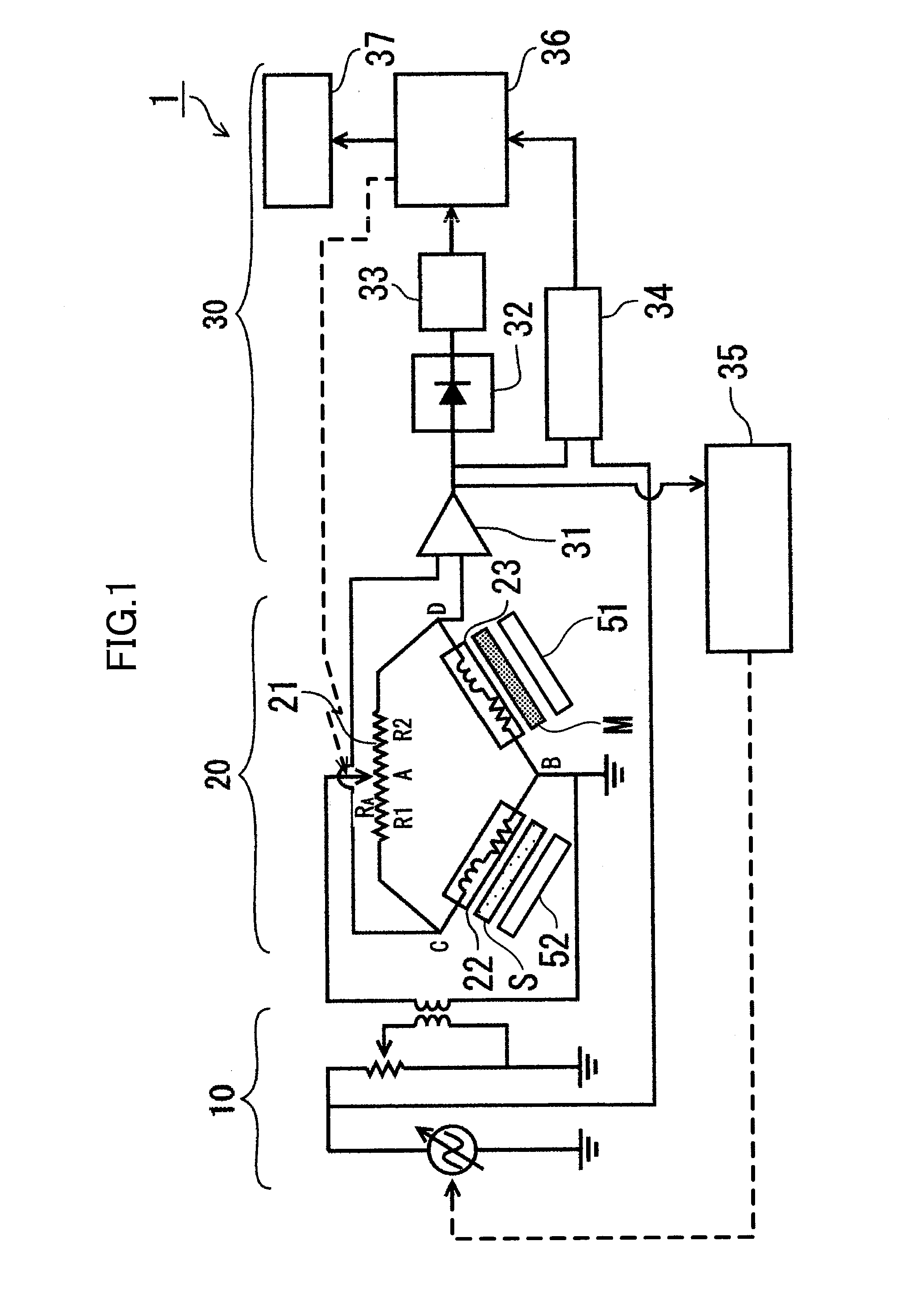
[0047]As shown in FIG. 1, the surface property inspection device 1 according to an embodiment of the present invention is furnished with an AC power supply 10, an AC bridge circuit 20, and a judgment device 30.

[0048]The AC power supply 10 is capable of supplying variable frequency AC power to the AC bridge circuit 20.

[0049]The AC bridge circuit 20 is furnished with a variable resistor 21, a benchmark detector 22 provided with a magnetic sensor for detecting the magnetic properties of a benchmark sample S, and an inspection detector 23 provided with a magnetic sensor for detecting magnetic properties of a sample under inspection M.

[0050]The variable resistor 21 is capable of variably splitting a resistance RA between resistors R1 and R2 in a split ratio γ. The resistors R1 and R2 form a bridge circuit together with the benchmark detector 22 and the inspection detector 23. In the present embodiment, the point A splitting resistor R1 and resistor R2, and point B between the benchmark d...


PUM

PropertyMeasurementUnit
surface propertyaaaaaaaaaa
AC poweraaaaaaaaaa
magnetic propertiesaaaaaaaaaa

Abstract

To provide a surface property inspection device and surface property inspection method with which the surface treatment condition of treated material such as steel subjected to such surface treatments as shot-peening treatment or heat treatment, nitriding, and the like can be non-destructively and precisely inspected, and which offers a high degree of general purpose application. A surface property inspection device 1 includes an AC power supply, an AC bridge circuit, and a judgment device, and the AC bridge circuit has a variable resistor with a variable split ratio γ, a benchmark detector, and an inspection detector. In variable resistor setting step S1, the split ratio γ of a variable resistor is adjusted and set so that the output from the AC bridge circuit is increased; after setting a frequency at which the output from the AC bridge circuit is maximized using a frequency setting step S2, in pass / fail judgment step S4, a benchmark sample S is brought into contact with the benchmark detector, the sample under inspection M is brought into contact with the inspection detector, and the output from the LPF 33 and the threshold value set in the threshold value setting step S3 are compared and a pass / fail judgment is made of the surface condition of the sample under inspection M.

Description

TECHNICAL FIELD[0001]The present invention pertains to a surface property inspection device and surface property inspection method for making a non-destructive pass / fail inspection of the surface treatment condition of processed material subjected to surface processing such as shot-peening or heat treatment, nitriding, or the like.BACKGROUND ART[0002]Surface treatments such as surface hardening by heat treatment, nitriding, and the like, or shot peening, are performed on gears, shafts, or other steel products used in automobile parts and the like to improve wear-resistance, fatigue strength, etc.[0003]Conventionally, evaluation of surface properties such as residual stress, hardness, and the like following surface treatment of these parts was done by sample destructive testing. This led to the problem that not all products could therefore not be directly tested, and because testing was destructive, tested products became unusable.[0004]There is therefore an increasing need to develo...

Claims


Application Information

Patent Timeline
Patent Type & Authority Applications(United States)
IPC IPC(8): G01N27/82
CPCG01N27/82G01B7/105G01N27/80G01N27/9046G01B7/06G01N27/90
Inventor MAKINO, YOSHIYASU
Owner SINTOKOGIO LTD
Learn More